Grundfos CR 5 Installation And Operating Instructions Manual

Typ
Installation And Operating Instructions Manual
CR, CRI, CRN
Installation and operating instructions
GRUNDFOS INSTRUCTIONS
2
Table of contents
3
CR, CRI, CRN
English (GB)
Installation and operating instructions . . . . . . . . . . . . . . . . . . . . . . . . . . . . . . . . . . . . . . . . . . . . . . . . . . . . . . . . . . . 5
 (BG)
    . . . . . . . . . . . . . . . . . . . . . . . . . . . . . . . . . . . . . . . . . . . . . . . . . . . . . . . . . 17
eština (CZ)
Montážní a provozní návod . . . . . . . . . . . . . . . . . . . . . . . . . . . . . . . . . . . . . . . . . . . . . . . . . . . . . . . . . . . . . . . . . . 29
Deutsch (DE)
Montage- und Betriebsanleitung . . . . . . . . . . . . . . . . . . . . . . . . . . . . . . . . . . . . . . . . . . . . . . . . . . . . . . . . . . . . . . 41
Dansk (DK)
Monterings- og driftsinstruktion . . . . . . . . . . . . . . . . . . . . . . . . . . . . . . . . . . . . . . . . . . . . . . . . . . . . . . . . . . . . . . . 53
Eesti (EE)
Paigaldus- ja kasutusjuhend . . . . . . . . . . . . . . . . . . . . . . . . . . . . . . . . . . . . . . . . . . . . . . . . . . . . . . . . . . . . . . . . . 65
Español (ES)
Instrucciones de instalación y funcionamiento. . . . . . . . . . . . . . . . . . . . . . . . . . . . . . . . . . . . . . . . . . . . . . . . . . . . 77
Suomi (FI)
Asennus- ja käyttöohjeet . . . . . . . . . . . . . . . . . . . . . . . . . . . . . . . . . . . . . . . . . . . . . . . . . . . . . . . . . . . . . . . . . . . . 89
Français (FR)
Notice d'installation et de fonctionnement . . . . . . . . . . . . . . . . . . . . . . . . . . . . . . . . . . . . . . . . . . . . . . . . . . . . . . 101
 (GR)
    . . . . . . . . . . . . . . . . . . . . . . . . . . . . . . . . . . . . . . . . . . . . . . . . . . . . . . . . 113
Hrvatski (HR)
Montažne i pogonske upute . . . . . . . . . . . . . . . . . . . . . . . . . . . . . . . . . . . . . . . . . . . . . . . . . . . . . . . . . . . . . . . . . 125
Magyar (HU)
Telepítési és üzemeltetési utasítás . . . . . . . . . . . . . . . . . . . . . . . . . . . . . . . . . . . . . . . . . . . . . . . . . . . . . . . . . . . 137
Italiano (IT)
Istruzioni di installazione e funzionamento. . . . . . . . . . . . . . . . . . . . . . . . . . . . . . . . . . . . . . . . . . . . . . . . . . . . . . 149
Lietuviškai (LT)
rengimo ir naudojimo instrukcija . . . . . . . . . . . . . . . . . . . . . . . . . . . . . . . . . . . . . . . . . . . . . . . . . . . . . . . . . . . . . 161
Nederlands (NL)
Installatie- en bedieningsinstructies . . . . . . . . . . . . . . . . . . . . . . . . . . . . . . . . . . . . . . . . . . . . . . . . . . . . . . . . . . . 173
Polski (PL)
Instrukcja montau i eksploatacji . . . . . . . . . . . . . . . . . . . . . . . . . . . . . . . . . . . . . . . . . . . . . . . . . . . . . . . . . . . . . 185
Português (PT)
Instruções de instalação e funcionamento. . . . . . . . . . . . . . . . . . . . . . . . . . . . . . . . . . . . . . . . . . . . . . . . . . . . . . 197
Român (RO)
Instruciuni de instalare i utilizare . . . . . . . . . . . . . . . . . . . . . . . . . . . . . . . . . . . . . . . . . . . . . . . . . . . . . . . . . . . . 209
Srpski (RS)
Uputstvo za instalaciju i rad . . . . . . . . . . . . . . . . . . . . . . . . . . . . . . . . . . . . . . . . . . . . . . . . . . . . . . . . . . . . . . . . . 221
 (RU)
,   
 . . . . . . . . . . . . . . . . . . . . . . . . . . . . . . . . . . . . . . . . . . . . . 233
Svenska (SE)
Monterings- och driftsinstruktion . . . . . . . . . . . . . . . . . . . . . . . . . . . . . . . . . . . . . . . . . . . . . . . . . . . . . . . . . . . . . 246
Slovensko (SI)
Navodila za montažo in obratovanje . . . . . . . . . . . . . . . . . . . . . . . . . . . . . . . . . . . . . . . . . . . . . . . . . . . . . . . . . . 258
Slovenina (SK)
Návod na montáž a prevádzku . . . . . . . . . . . . . . . . . . . . . . . . . . . . . . . . . . . . . . . . . . . . . . . . . . . . . . . . . . . . . . 270
Türkçe (TR)
Montaj ve kullanım kılavuzu . . . . . . . . . . . . . . . . . . . . . . . . . . . . . . . . . . . . . . . . . . . . . . . . . . . . . . . . . . . . . . . . . 282
Table of contents
4
CR, CRI, CRN
 (UA)
    . . . . . . . . . . . . . . . . . . . . . . . . . . . . . . . . . . . . . . . . . . . . . . . . . . . . . . . . . 295
 (KZ)
    . . . . . . . . . . . . . . . . . . . . . . . . . . . . . . . . . . . . . . . . . . . . . . . . . . . . . 307
 (AR)
   . . . . . . . . . . . . . . . . . . . . . . . . . . . . . . . . . . . . . . . . . . . . . . . . . . . . . . . . . . . . . . . . 330
Appendix . . . . . . . . . . . . . . . . . . . . . . . . . . . . . . . . . . . . . . . . . . . . . . . . . . . . . . . . . . . . . . . . . . . . . . . . . . . . . . . 331
Appendix . . . . . . . . . . . . . . . . . . . . . . . . . . . . . . . . . . . . . . . . . . . . . . . . . . . . . . . . . . . . . . . . . . . . . . . . . . . . . . . 351
Declaration of conformity . . . . . . . . . . . . . . . . . . . . . . . . . . . . . . . . . . . . . . . . . . . . . . . . . . . . . . . . . . . . . . . . . . . 359
Declaration of conformity EAC . . . . . . . . . . . . . . . . . . . . . . . . . . . . . . . . . . . . . . . . . . . . . . . . . . . . . . . . . . . . . . . 361
Declaration of conformity EAC . . . . . . . . . . . . . . . . . . . . . . . . . . . . . . . . . . . . . . . . . . . . . . . . . . . . . . . . . . . . . . . 362
English (GB)
5
English (GB) Installation and operating instructions
Original installation and operating instructions
CONTENTS
Page
1. Symbols used in this document
2. Handling
When lifting the entire pump with motor, follow these instructions:
Pump with motor sizes 0.37 - 5.5 kW:
Lift the pump in the motor flange by means of straps or the
like.
Pump with motor sizes 7.5 - 22 kW:
Lift the pump by means of the motor eyebolts.
Pump with motor sizes 30-45 kW:
Lift the pump by means of the lifting brackets on the motor
flange.
Pump with motor sizes 55-75 kW:
Lift the pump by means of the eyebolts on the motor side.
Fig. 1 Correct lifting of a CR pump
In case of CR, CRI and CRN pumps with other motors than MG or
Siemens, we recommend that you to lift the pump by means of
the straps in the motor flange.
1. Symbols used in this document
5
2. Handling
5
3. Type designation
6
3.1 Type key for CR, CRI, CRN 1s, 1, 3, 5, 10, 15 and 20
6
3.2 Type key for CR, CRN 32, 45, 64, 90, 120 and 150
6
4. Applications
6
5. Technical data
6
5.1 Ambient temperature and altitude
6
5.2 Liquid temperature
7
5.3 Maximum permissible operating pressure and liquid
temperature for the shaft seal
7
5.4 Minimum inlet pressure
7
5.5 Minimum inlet pressure
7
5.6 Minimum flow rate
8
5.7 Electrical data
8
5.8 Frequency of starts and stops
8
5.9 Dimensions and weights
8
5.10 Sound pressure level
8
6. Installation
8
6.1 Foundation
9
6.2 Vibration dampening
10
6.3 Outdoor installation
10
6.4 Hot or cold surfaces
10
6.5 Torques
10
6.6 Flange forces and torques
11
7. Electrical connection
12
7.1 Cable entry/screwed connection
12
7.2 Three-phase connection
12
7.3 Single-phase connection
13
7.4 Terminal box positions
13
7.5 Frequency converter operation
13
8. Startup
14
8.1 Shaft seal run-in
14
9. Maintenance
14
10. Frost protection
15
11. Service
15
11.1 Service kits and manuals
15
12. Fault finding
16
13. Disposing of the product
16
Warning
Prior to installation, read these installation and
operating instructions. Installation and operation
must comply with local regulations and accepted
codes of good practice.
Warning
If these safety instructions are not observed, it may
result in personal injury.
Warning
If these instructions are not observed, it may lead to
electric shock with consequent risk of serious
personal injury or death.
Warning
The surface of the product may be so hot that it may
cause burns or personal injury.
Caution
If these safety instructions are not observed, it may
result in malfunction or damage to the equipment.
Note
Notes or instructions that make the job easier and
ensure safe operation.
TM04 0339 0608
TM04 0341 0608
TM05 9564 4113
TM04 0341 0608
0.37 - 5.5 kW 7.5 - 22 kW 30-45 kW 55-75 kW
Warning
Make sure that the pump remains in a stable position
during unpacking and installation by means of the
straps used for lifting the pump.
Note that typically the centre of gravity of the pump is
close to the motor.
English (GB)
6
3. Type designation
3.1 Type key for CR, CRI, CRN 1s, 1, 3, 5, 10, 15 and 20
3.2 Type key for CR, CRN 32, 45, 64, 90, 120 and 150
4. Applications
Grundfos multistage in-line centrifugal pumps, types CR, CRI and
CRN, are designed for a wide range of applications.
CR, CRI, CRN
CR, CRI and CRN pumps are suitable for liquid transfer,
circulation and pressure boosting of cold or hot clean liquids.
CRN
Use CRN pumps in systems where all parts in contact with the
liquid are made of high-grade stainless steel.
Pumped liquids
Thin, clean, non-flammable, non-combustible or non-explosive
liquids, not containing solid particles or fibres. The liquid must not
attack the pump materials chemically.
When pumping liquids with a density and/or viscosity higher than
that of water, use motors with correspondingly higher outputs, if
required.
5. Technical data
5.1 Ambient temperature and altitude
If the ambient temperature exceeds the above temperature
values or the pump is installed at an altitude exceeding the above
altitude values, the motor must not be fully loaded due to the risk
of overheating. Overheating may result from excessive ambient
temperatures or the low density and consequently low cooling
effect of the air.
In such cases, it may be necessary to use a motor with a higher
rated output.
Fig. 2 Motor output depends on temperature/altitude
Example
Figure 2 shows that the load of an IE3 motor at an ambient
temperature of 70 °C must not be loaded more than 89 % of the
rated output. If the pump is installed 4750 metres above sea
level, the motor must not be loaded more than 89 % of the rated
output.
In cases where both the maximum temperature and the maximum
altitude are exceeded, the derating factors must be multiplied
(0.89 x 0.89 = 0.79).
Example CR3-10X-X-X-X-XXXX
Type range: CR, CRI, CRN
Rated flow rate in m
3
/h
Number of impellers
Code for pump version
Code for pipework connection
Code for materials
Code for rubber pump parts
Code for shaft seal
Example CR 32- 2 1- X- X- X- X- XXXX
Type range: CR, CRN
Rated flow rate in m
3
/h
Number of stages
Number of impellers with reduced diameter
Code for pump version
Code for pipework connection
Code for materials
Code for rubber pump parts
Code for shaft seal
Warning
The pumping media is not suitable for the pump as it
can cause injury to persons or damage to the
equipment.
Motor
power
[kW]
Motor
make
Motor
efficiency
class
Maximum
ambient
temperature
[°C]
Maximum
altitude
above sea
level
[m]
0.37 - 0.55
Grundfos
MG
- +40 1000
0.75 - 22
Grundfos
MG
IE3 +60 3500
30-75 Siemens IE3 +55 2750
TM03 2479 4405
Pos.
Motor power
[kW]
Motor make
1
0.37 - 0.55 MG
0.37 - 22 MGE
20.75 - 22 MG
3 30-75 Siemens
Note
For motor bearing maintenance at ambient
temperatures above 40 °C, see section
9. Maintenance.
20 25 30 35 40 45 50 55 60 65 70 75 80
50
60
70
80
90
100
[%]
P2
2
1
t [°C]
1000 2250 3500 4750 m
3
English (GB)
7
5.2 Liquid temperature
The table on page 333 states the relationship between liquid
temperature range and maximum permissible operating pressure.
5.3 Maximum permissible operating pressure and
liquid temperature for the shaft seal
CR, CRI, CRN 1s to 20 and CR, CRN 32 to 150
Fig. 3 Maximum permissible operating pressure and liquid
temperature
You can clean CRI and CRN pumps in place (CIP) with a type H
shaft seal with EPDM rubber parts, HxxE and liquids up to 150 °C
for maximum 15 minutes.
CR, CRI, CRN pumps are not suitable for the pumping of liquids
above 120 °C for long periods.
5.4 Minimum inlet pressure
Fig. 4 Schematic view of open system with a CR pump
Calculate the maximum suction lift "H" in metres head as follows:
H = p
b
x 10.2 - NPSH - H
f
- H
v
- H
s
p
b
= Barometric pressure in bar.
Barometric pressure can be set to 1 bar.
In closed systems, p
b
indicates the system pressure in
bar.
NPSH = Net Positive Suction Head in metres head.
To be read from the NPSH curve on page 331 at the
highest flow the pump will be delivering.
H
f
= Friction loss in inlet pipe in metres head at the highest
flow the pump will be delivering.
H
v
= Vapour pressure in metres head, see fig. E on page
336. t
m
= liquid temperature.
H
s
= Safety margin = minimum 0.5 metres head.
If the calculated "H" is positive, the pump can operate at a suction
lift of maximum "H" metres head.
If the calculated "H" is negative, an inlet pressure of minimum "H"
metres head is required. There must be a pressure equal to the
calculated "H" during operation.
Example
p
b
= 1 bar.
Pump type: CR 15, 50 Hz.
Flow rate: 15 m
3
/h.
NPSH (from page 331): 1.1 metres head.
H
f
= 3.0 metres head.
Liquid temperature: +60 °C.
H
v
(from fig. E, page 336): 2.1 metres head.
H = p
b
x 10.2 - NPSH - H
f
- H
v
- H
s
[metres head].
H = 1 x 10.2 - 1.1 - 3.0 - 2.1 - 0.5 = 3.5 metres head.
This means that the pump can operate at a suction lift of
maximum 3.5 metres head.
Pressure calculated in bar: 3.5 x 0.0981 = 0.343 bar.
Pressure calculated in kPa: 3.5 x 9.81 = 34.3 kPa.
5.5 Minimum inlet pressure
The table on page 334 states the maximum permissible inlet
pressure. However, the actual inlet pressure + maximum pump
pressure (at no flow) must always be lower than the values stated
in fig. A, page 333.
The pumps are pressure-tested at a pressure of 1.5 times the
values stated in fig. B, page 334.
Note
The maximum permissible operating pressure and
liquid temperature ranges apply to the pump only.
Note
The diagram below applies to clean water and water
containing anti-freeze liquids.
TM03 8853 4907
Standard shaft seal
Motor
[kW]
Max. temperature range
[°C]
HQQE 0.37 - 45 -40 - 120 °C
HBQE 55-75 0-120 °C
HQQV 0.37 - 45 -20 - 90 °C
HBQV 55-75 0-90 °C
Note
The pumping of liquids above +120 °C may result in
periodical noise and reduced pump life.
-60 -40 -20 0 20 40 60 80 100 120 140
0
5
10
15
20
25
30
35
p [bar]
HQQE/V
HBQE/V
H
Q
Q
E
H
Q
Q
E
H
B
Q
E
H
Q
Q
V
H
Q
Q
E
t [°C]
TM02 0118 3800
Hv
H
NPSH
Pb
Hf
English (GB)
8
5.6 Minimum flow rate
Due to the risk of overheating, do not use the pump at flows
below the minimum flow rate.
The curves below show the minimum flow rate as a percentage of
the rated flow rate in relation to the liquid temperature.
- - - - = air-cooled top.
Fig. 5 Minimum flow rate
5.7 Electrical data
See motor nameplate.
5.8 Frequency of starts and stops
5.9 Dimensions and weights
Dimensions: See fig. C, page 335.
Weights: See label on the packing.
5.10 Sound pressure level
See fig. D, page 336.
6. Installation
The pump must be secured to a horizontal, plane and solid
foundation by bolts through the holes in the base plate. When
installing the pump, follow the procedure below in order to avoid
damaging the pump.
TM01 2816 2302
Caution
The pump must not run against a closed outlet valve.
Motor size
[kW]
Maximum number of starts per hour
2.2 250
3-4 100
5.5 - 11 50
18.5 - 22 40
30 90
37 50
45 80
55 50
75 50
Step Action
1
TM02 0013 3800
Arrows on the pump base show
the direction of flow of liquid
through the pump.
2
TM00 2256 3393
This information is stated on
page 335:
port-to-port lengths
dimensions of the base
pipework connections
diameter and position of
foundation bolts.
40 60 80 100 120 140 160 180
t [°C]
0
10
20
30
Qmin
[%]
2
1
2
1
L
L
B
4 x ø
B
3
TM01 1241 4097
You can install the pump
vertically or horizontally. CR,
CRN 120 and 150, 75 kW, only
vertically. However, the motor
must neither fall below the
horizontal plane nor be
installed upside down.
Make sure that an adequate
supply of cool air reaches the
motor cooling fan.
Motors above 4 kW must be
supported.
3a
TM05 7705 1013
Additional support. As the
centre of gravity on the pump is
relative high, we recommend
that pumps installed on ships,
in areas with risk of earth
quake or in systems which has
to be moved are equipped with
additional support brackets.
You can fit the bracket from the
motor stool to the bulkhead of
the ship, a rigid wall in a
building or to a rigid part.
4
TM02 0116 3800
To minimise possible noise
from the pump, we advise you
to fit expansion joints on either
side of the pump.
Carry out the foundation or
installation as described in
section 6.1 Foundation.
Fit the isolating valves on
either side of the pump to avoid
draining the system if the pump
needs to be removed for
cleaning, repair or
replacement.
Always protect the pump
against backflow by means of a
non-return valve.
5
TM02 0114 3800
Install the pipes so that air
locks do not occur, especially
on the inlet side of the pump.
6
TM02 0115 3800
Fit a vacuum valve close to the
pump if the installation has one
of these characteristics:
The outlet pipe slopes
downwards away from the
pump.
There is a risk of siphon
effect.
Protection against backflow
of unclean liquids is needed.
Step Action
English (GB)
9
6.1 Foundation
Grundfos recommends that you install the pump on a concrete
foundation which is heavy enough to provide permanent and rigid
support to the entire pump. The foundation must be capable of
absorbing any vibration, normal strain or shock. The concrete
foundation must have an absolutely level and even surface.
Place the pump on the foundation, and fasten it. The base plate
must be supported on the whole area.
The following instruction applies when mounting the pump in
vertical or horizontal position.
Place the pump on the foundation, and fasten it. See fig. 6.
Fig. 6 Correct installation
Fig. 7 Foundation, vertical mounting
The recommended length and width are shown in fig. 7. Note that
the length and width of the foundation for pumps with motor size
below or equal to 30 kW must be 200 mm larger than the base
plate.
For pumps with motor size above or equal to 37 kW, the length
and width must always be 1.5 x 1.5 (L
f
x B
f
) metres.
Fig. 8 Foundation, horizontal mounting
The foundation length and width must always be 200 mm larger
than the length and width of the pump. See fig. 8.
The mass of the foundation must be at least 1.5 times the total
mass of the pump. The minimum height of the foundation (h
f
) can
then be calculated:
The density (δ) of concrete is usually taken as 2200 kg/m
3
.
In installations where noise-less operation is particularly
important, we recommend that you use a foundation with a mass
up to 5 times that of the pump.
The foundation must be provided with bolts for fixing the base
plate. See fig. 9.
Fig. 9 Bolt in foundation
When the foundation bolts are in position, place the pump on the
foundation. Then align the base plate using shims, if necessary,
so that it is completely horizontal. See fig. 10.
Fig. 10 Alignment with shims
Warning
To avoid personal injury, make sure that the pump is
mounted securely in all conditions.
Warning
Carry out the foundation or installation in accordance
with the following instructions.
TM04 0342 0608TM04 0343 0608
TM05 9579 4113
h
f
=
m
pump
× 1.5
L
f
× B
f
× δ
concrete
TM03 4589 2206TM04 0362 0608
Shims
English (GB)
10
6.2 Vibration dampening
If you use vibration dampers, install them under the foundation.
Pumps with motor size below or equal to 30 kW can use vibration
dampers as shown in fig. 11.
For pumps with motor sizes above or equal to 37 kW, use a
Sylomer
®
plate as shown in fig. 12.
Fig. 11 Pump on vibration dampers
Fig. 12 Pump on Sylomer
®
plate
6.3 Outdoor installation
When installed outdoors, we recommend that you provide the
motor with a rain cover. We also recommend that you open one of
the drain holes in the motor flange.
6.4 Hot or cold surfaces
Figure 13 shows which pump parts get as hot or cold as the
pumped liquid.
Fig. 13 Hot or cold surfaces on a CR, CRI, CRN pump
6.5 Torques
The table shows the recommended torques for bolts in base and
flanges.
The bolt quality must be minimum 8.8.
TM04 1691 1008TM04 1692 1008
Vibration dampers
Sylomer
®
plate
Warning
When pumping hot or cold liquids, make sure that
persons cannot accidentally come into contact with
hot or cold surfaces.
TM04 0361 0608
Caution
To minimize risk of damage to the equipment, make
sure to tighten bolts according to recommendations.
CR, CRI, CRN
Base
[Nm]
Flange [Nm]
DIN, JIS, ANSI Oval
1s-5 40 M10 - 50-60
10-20 50 M12 60 60-70
32-150 70 M16 100 70-80
M20 150 -
M24 200 -
Pump head
Pump sleeve
Base
English (GB)
11
6.6 Flange forces and torques
If not all loads reach the maximum permissible value stated in the
tables below, one of these values may exceed the normal limit.
Contact Grundfos for further information.
Fig. 14 Flange forces and torques
Forces
The following tables represent values that applies according to
the material quality.
TM04 0346 2013
Y-direction: Inlet/outlet
Z-direction: Direction of chamber stack
X-direction: 90 ° from inlet/outlet
Force limits for CR cast-iron pump housing
Flange, DN
[mm]
CR
Force, Y-direction
[N]
Force, Z-direction
[N]
Force, X-direction
[N]
25/32 1s-5 338 394 319
40 10 413 469 375
50 15 and 20 563 581 506
65 32 694 788 638
80 45 938 769 844
100 64 and 90 1256 1013 1125
125/150 120 and 150 1256 1013 1125
Torque limits to CR cast-iron pump housing
Flange, DN
[mm]
CR
Torque, Y-direction
[Nm]
Torque, Z-direction
[Nm]
Torque, X-direction
[Nm]
25/32 1s-5 300 175 125
40 10 400 275 200
50 15 and 20 450 325 250
65 32 500 350 300
80 45 325 400 550
100 64 and 90 375 475 625
125/150 120 and 150 375 475 625
Force limits for CRI, CRN stainless-steel pumps housing
Flange, DN
[mm]
CRI, CRN
Force, Y-direction
[N]
Force, Z-direction
[N]
Force, X-direction
[N]
25/32 1s-5 675 788 638
40 10 825 938 750
50 15 and 20 1125 1163 1013
65 32 1388 1575 1275
80 45 1875 1538 1688
100 64 and 90 2513 2025 2250
125/150 120 and 150 2513 2025 2250
Torque limits to CRI, CRN stainless steel pump housing
Flange, DN
[mm]
CRI, CRN
Torque, Y-direction
[Nm]
Torque, Z-direction
[Nm]
Torque, X-direction
[Nm]
25/32 1s-5 600 350 250
40 10 800 550 400
50 15 and 20 900 650 500
65 32 1000 700 600
80 45 650 800 1100
100 64 and 90 750 950 1250
125/150 120 and 150 750 950 1250
English (GB)
12
7. Electrical connection
The electrical connection must be carried out by an authorised
electrician in accordance with local regulations.
The operating voltage and frequency are marked on the motor
nameplate. Make sure that the motor is suitable for the power
supply on which it will be used and the motor terminal connection
is correct. You will find a wiring diagram in the terminal box.
7.1 Cable entry/screwed connection
All motors are supplied without screwed cable entries. The table
below shows the numbers and sizes of cable entry holes of the
terminal box (standard EN 50262).
7.2 Three-phase connection
1)
60 Hz motors, 0.37 - 1.1 kW: 220-277/380-440 V.
Fig. 15 Delta connection
Fig. 16 Star connection
If the motor is provided with PTC sensors or PTO contacts, the
connection must be in accordance with the wiring diagram in the
terminal box.
Connect three-phase motors to a motor-protective circuit breaker.
Warning
Connect the CR pump to an external mains switch
placed close to the pump and to a motor-protective
circuit breaker or a CUE frequency converter. Make
sure you can lock the mains switch in OFF position
(isolated). Type and requirements as specified in EN
60204-1, 5.3.2.
Warning
Before removing the terminal box cover and before
removing or dismantling the pump, make sure that
the power supply has been switched off and that it
cannot be accidentally switched on.
Caution
Consider whether it is necessary to install an
emergency stop switch.
Motor
[kW]
Number and size
of cable entries
Description
0.25 - 0.55 2 x M20 x 1.5
The holes have precast
threads and are closed with
knock-out cable entries
0.75 - 3.0 2 x M20
The holes are closed with
knock-out cable entries
4.0 - 7.5 4 x M25
The holes are closed with
knock-out cable entries
11-22
2 x M20
4 x M40
The holes are closed with
knock-out cable entries
30-45 2 x M50 x 1.5 Blanking plug
55-75 2 x M63 x 1.5 Blanking plug
Mains supply [V]
Delta connection Star connection
50 Hz
220-240 / 380-415
380-415 / 660-690
60 Hz
220-277 / 380-480
1)
380-480 / 660-690
TM02 6656 1305TM02 6655 1305
W2
U2
V2
U1
U1
V1
V1
W1
U2
V2
W1
W2
L
3
L
2
L
1
English (GB)
13
7.3 Single-phase connection
Fig. 17 Connection, "low voltage", 0.37 - 0.75 kW
Fig. 18 Connection, "high voltage", 0.37 - 0.75 kW
Fig. 19 Connection, "low voltage", 1.1 - 2.2 kW
Fig. 20 Connection, "high voltage", 1.1 - 2.2 kW
Single-phase Grundfos motors incorporate a thermal switch and
require no additional motor protection.
7.4 Terminal box positions
You can turn the terminal box to four positions, in 90 ° steps.
Follow this procedure:
1. If necessary, remove the coupling guards. Do not remove the
coupling.
2. Remove the bolts securing the motor to the pump.
3. Turn the motor to the required position.
4. Replace and tighten the bolts.
5. Replace the coupling guards.
Carry out the electrical connection as shown in the diagram
inside the terminal box cover.
7.5 Frequency converter operation
You can use 3-phase motors for frequency convertor operation
following the conditions below. This section applies to motors
defined in IEC 60034.
7.5.1 General conditions
Protect all motors used with frequency converters against voltage
peaks and dU/dt according to IEC 60034-17. Grundfos
recommends that you use insulated bearings for motors from
frame size 225 (45 kW/2-pole, 30 kW/4-pole and 22 kW/6-pole).
Mains voltage dependent conditions
200-240 V
No output filters are required for frequency converter operated
motors with mains voltages up to 240 V.
380-500 V
For frequency converter operated motors with motor cable length
less than 25 metres and mains supply up to 460 V. No additional
motor protection against voltage peaks is required. For frequency
converter operated motors with motor cable length of more than
25 metres or mains supply higher than 460 V, sine-wave filters
are required.
500 V and higher
Always use sine-wave filters for motors marked with 500 V or
higher voltages. *
Exception
Protect Grundfos motors types MG 71 and MG 80 (up to 1.1
kW/2-pole and up to 0.75 kW/4-pole) for supply voltages up to
and including 440 V without phase insulation against voltage
peaks above 650 V between the supply terminals.
If you use MG 71 and MG 80 without phase insulation for input
voltages above 240 V, it requires that you use sine save filters
at the output of the frequency converter.
MG 71 and MG 80 with phase insulation for use with variable
frequency drives are available as standard products.
* Motors with reinforced insulation can be supplied as an option.
These motors are according to IEC 60034-25 and therefore there
is no need for sine-wave filters. This do not eliminate the
requirement for insulated bearings from frame size 225.
7.5.2 Motors supplied by Grundfos
You can connect all three-phase MG motors with phase insulation
to a frequency converter.
Mains supply [V]
"Low voltage" "High voltage"
50 Hz 220-230 / 240
TM04 1693 1008TM04 1694 1008TM04 0345 0608TM04 0344 0608
English (GB)
14
7.5.3 Phase insulation, MG 71 and 80
MG motors, frame sizes 71 and 80, do not have phase insulation
as standard. The motors are not suitable for frequency converter
operation as they are not protected against the voltage peaks
caused by the frequency converter operation. Only motors with a
rated voltage equal to or above 460 V have phase insulation.
We recommend that you protect all other motors against voltage
peaks higher than 1200 V by 2000 V/μsec.
You can eliminate the above disturbances, i.e. both increased
acoustic noise and detrimental voltage peaks by fitting an LC filter
between the frequency converter and the motor.
For further information, contact the frequency converter or motor
supplier.
7.5.4 Other motor makes than those supplied by Grundfos
Contact Grundfos or the motor manufacturer.
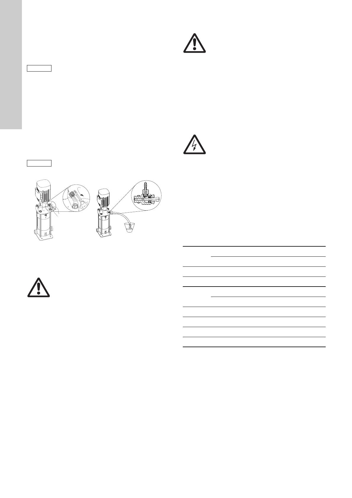
8. Startup
Fig. 21 Vent valve, standard and an optional solution with
hose connection
Follow the instructions on page 351.
CR, CRI, CRN 1s to 5
For these pumps, we advise you to open the bypass valve during
startup. See fig. 22 for bypass valve location. The bypass valve
connects the inlet and outlet sides of the pump, thus making the
filling procedure easier. Close the bypass valve again when the
operation is stable.
When pumping liquids containing air, we advise you to leave the
bypass valve open if the operating pressure is lower than 6 bar.
Close the bypass valve if the operating pressure constantly
exceeds 6 bar. Otherwise the material at the opening will be worn
because of the high liquid velocity.
8.1 Shaft seal run-in
The seal faces are lubricated by the pumped liquid, meaning that
there may be a certain amount of leakage from the shaft seal.
When you start the pump for the first time, or when you install a
new shaft seal, a certain run-in period is required before the
leakage is reduced to an acceptable level. The time required for
this depends on the operating conditions, i.e. every time the
operating conditions change, a new run-in period will be started.
Under normal conditions, the leaking liquid will evaporate. As a
result, no leakage will be detected.
9. Maintenance
Pump bearings and shaft seal are maintenance-free.
Motor bearings
Motors not fitted with grease nipples are maintenance-free.
Motors fitted with grease nipples must be lubricated with a high-
temperature, lithium-based grease. See the instructions on the
fan cover.
In the case of seasonal operation where the motor is idle for more
than 6 months of the year, we recommend that you grease the
motor when you take the pump out of operation.
Depending on the ambient temperature, replace or lubricate the
motor bearings according to the table below. The table applies to
2-pole motors. The number of operating hours stated for bearing
replacement are guidelines only.
Intervals for 4-pole motors are twice as long as those for 2-pole
motors.
If the ambient temperature is lower than 40 °C, then replace or
lubricate the bearings at the intervals mentioned under 40 °C.
Caution
Frequency converter operation of MG motors without
phase insulation will cause damage to the motor.
Caution
Do not start the pump until it has been filled with
liquid and vented. If the pump runs dry, the pump
bearings and the shaft seal may be damaged.
TM05 1160 0611 - TM05 8098 1913
Warning
Pay attention to the direction of the vent hole and
make sure that the escaping water does not cause
injury to persons or damage to the motor or other
components.
In hot-water installations, pay special attention to the
risk of injury caused by scalding hot water.
Warning
Make sure that a leakage does not cause injury to
persons or damage to the equipment.
Warning
Before starting work on the pump, make sure that all
power supplies to the pump have been switched off
and that they cannot be accidentally switched on.
Motor size
[kW]
Bearing replacement interval [operating hours]
40 °C 45 °C 50 °C 55 °C 60 °C
0.37 - 0.75 18000----
1.1 - 7.5 20000 15500 12500 10000 7500
Motor size
[kW]
Lubrication interval [operating hours]
40 °C 45 °C 50 °C 55 °C 60 °C
11 - 18.5 4500 3400 2500 1700 1100
22 4000 3100 2300 1500 1000
30-55 4000 3000 2000 1500 -
75 2000 1500 1000 500 -
English (GB)
15
10. Frost protection
Drain pumps which are not being used during periods of frost to
avoid damage.
Drain the pump by loosening the vent screw in the pump head
and by removing the drain plug from the base.
Do not tighten the vent screw and replace the drain plug until the
pump is to be used again.
CR, CRI, CRN 1s to 5
Before replacing the drain plug in the base, screw the bypass
valve out against the stop. See fig. 22.
Fig. 22 Location of drain plug and bypass valve
Fit the drain plug by tightening the large union nut followed by the
bypass valve.
11. Service
We recommend that you repair pumps with motors of 7.5 kW and
up at pump site. Necessary lifting equipment must be available.
If Grundfos is requested to service the pump, contact Grundfos
with details about the pumped liquid, etc. before the pump is
returned for service. Otherwise, Grundfos can refuse to accept
the pump for service.
Possible costs of returning the pump are to be paid by the
customer.
However, any application for service, no matter to whom it may
be made), must include details about the pumped liquid if you
have used the pump for liquids which are toxic or injurious to
health.
11.1 Service kits and manuals
Service documentation is available in Grundfos Product Center
(http://product-selection.grundfos.com/).
If you have any questions, please contact the nearest Grundfos
company or service workshop.
Warning
Pay attention to the direction of the vent hole and
make sure that the escaping water does not cause
injury to persons or damage to the motor or other
components.
In hot-water installations, pay special attention to the
risk of injury caused by scalding hot water.
TM01 1243 4097
Drain plug
Bypass valve
Note
If you have used a pump for a liquid which is toxic or
injurious to health, the pump will be classified as
contaminated.
English (GB)
16
12. Fault finding
13. Disposing of the product
This product or parts of it must be disposed of in an
environmentally sound way:
1. Use the public or private waste collection service.
2. If this is not possible, contact the nearest Grundfos company
or service workshop.
Subject to alterations.
Warning
Before removing the terminal box cover and before
removing or dismantling the pump, make sure that
the power supply has been switched off and that it
cannot be accidentally switched on.
Fault Cause Remedy
1. Motor does not run
when started.
a) Supply failure. Connect the power supply.
b) The fuses are blown. Replace fuses.
c) The motor-protective circuit breaker has tripped. Reactivate the motor-protective circuit breaker.
d) The thermal protection has tripped. Reactivate the thermal protection.
e) The main contacts in the motor-protective circuit
breaker are not making contact or the coil is
faulty.
Replace contacts or magnetic coil.
f) The control circuit is defective. Repair the control circuit.
g) The motor is defective. Replace the motor.
2. Motor-protective circuit
breaker trips
immediately when
power supply is
switched on.
a) One fuse is blown or the automatic circuit
breaker is tripped.
Replace the fuse or cut in the circuit breaker.
b) The contacts in the motor-protective circuit
breaker are faulty.
Replace motor-protective circuit breaker contacts.
c) The cable connection is loose or faulty. Fasten or replace the cable connection.
d) The motor winding is defective. Replace the motor.
e) The pump is mechanically blocked. Remove the mechanical blocking of the pump.
f) The motor-protective circuit breaker setting is
too low.
Set the motor-protective circuit breaker correctly.
3. Motor-protective circuit
breaker trips
occasionally.
a) The motor-protective circuit breaker setting is
too low.
Set the motor-protective circuit breaker correctly.
b) Low voltage at peak times. Check the power supply.
4. Motor-protective circuit
breaker has not tripped
but the pump does not
run.
a) Check 1 a), b), d), e) and f).
5. Pump performance not
constant.
a) The pump inlet pressure is too low (cavitation). Check the inlet conditions.
b) The inlet pipe or pump is partly blocked by
impurities.
Clean the inlet pipe or pump.
c) The pump draws in air. Check the inlet conditions.
6. Pump runs but gives no
water.
a) The inlet pipe or pump is blocked by impurities. Clean the inlet pipe or pump.
b) The foot or non-return valve is blocked in closed
position.
Repair the foot or non-return valve.
c) There is a leakage in the inlet pipe. Repair the inlet pipe.
d) There is air in the inlet pipe or pump. Check the inlet conditions.
e) The motor runs in the wrong direction of
rotation.
Change the direction of rotation of the motor.
7. Pump runs backwards
when switched off.
a) There is a leakage in the inlet pipe. Repair the inlet pipe.
b) The foot or non-return valve is defective. Repair the foot or non-return valve.
8. Leakage in shaft seal. a) The shaft seal is defective. Replace the shaft seal.
9. Noise. a) Cavitation. Check the inlet conditions.
b) The pump does not rotate freely due to frictional
resistance, as a result of incorrect pump shaft
position.
Adjust the pump shaft.
Follow the procedure in fig. F, G or H at the end of
these instructions.
c) Frequency converter operation. See section 7.5 Frequency converter operation.
 (BG)
17
 (BG)    
    

.
1.   
2. 
    , 
 - :
    0,37 - 5,5 kW:
    ,  
  .
    7,5 - 22 kW:
 ,     
 .
    30-45 kW:
 , 
   
   .
    55-75 kW:
 ,     
  .
. 1     CR
   CR, CRI CRN  ,  
 MG  Siemens,     
   
  .
1.   
17
2. 
17
3.   
18
3.1     CR, CRI, CRN 1s, 1, 3, 5, 10, 15 20
18
3.2     CR, CRN 32, 45, 64, 90, 120 150
18
4. 
18
5.  
18
5.1    
18
5.2   
19
5.3    
      
19
5.4
  
19
5.5   
19
5.6  
20
5.7  
20
5.8    
20
5.9  
20
5.10    
20
6. 
20
6.1 
21
6.2   
22
6.3   
22
6.4    
22
6.5  
22
6.6     
23
7.  
24
7.1   / 
24
7.2  
24
7.3  
25
7.4    
25
7.5   
25
8. 
26
8.1     
26
9. 
26
10.   
27
11. 
27
11.1   
27
12.   
28
13.   
28

 ,    
 . 
    
   
.

       ,
     .

      
  ,    
   .

      
     
.
Внимание
     
       
.
Указание
 ,   
  .
TM04 0339 0608
TM04 0341 0608
TM05 9564 4113
TM04 0341 0608
0,37 - 5,5 kW 7,5 - 22 kW 30-45 kW 55-75 kW

     
    
  ,   
 .
 ,    
     .
 (BG)
18
3.   
3.1     CR, CRI, CRN 1s, 1, 3, 5, 10, 15 20
3.2     CR, CRN 32, 45, 64, 90, 120 150
4. 
     Grundfos
 CR, CRI, CRN      
.
CR, CRI, CRN
 CR, CRI CRN      ,
      
.
CRN
 CRN  ,  
     
  .
 
, ,   
,     .
      
   .
    / , -
    ,   
- ,  .
5.  
5.1    
     -
     ,
  -,    
      .
       
     
     
 
.
      
 -  .
. 2      /
  

 2 ,     IE3 
  70 °C     89 % 
  .   

4750   ,   
    89 %   
.
,     
   ,
      (0,89 x 0,89
= 0,79).
 CR 3- 10 X- X- X- X- XXXX
  : CR, CRI,
CRN
  m
3
/h
   
    
    
  
    
    
 CR 32- 2 1- X- X- X- X- XXXX
  : CR,
CRN
  m
3
/h
 
    

    
    
  
    
    

     ,
      
    .
 

[kW]


 

 



[°C]



[m]
0,37 - 0,55
Grundfos
MG
- +40 1000
0,75 - 22
Grundfos
MG
IE3 +60 3500
30-75 Siemens IE3 +55 2750
TM03 2479 4405
.
 

[kW]
 
1
0,37 - 0,55 MG
0,37 - 22 MGE
20,75 - 22 MG
3 30-75 Siemens
Указание
     
    40 °C  
9. Поддръжка.
20 25 30 35 40 45 50 55 60 65 70 75 80
50
60
70
80
90
100
[%]
P2
2
1
t [°C]
1000 2250 3500 4750 m
3
 (BG)
19
5.2   
  . 333     
    
 .
5.3    
     

CR, CRI, CRN 1s  20 CR, CRN 32  150
. 3    
  
     (CIP)  CRI CRN
     H EPDM  , HxxE,
   150 °C   15 .
 CR, CRI, CRN      
   120 °C    
.
5.4   
. 4     CR 
    "" 
   :
H=p
b
x 10,2 - NPSH - H
f
- H
v
- H
s
p
b
=   bar.
      
 1 bar.
  p
b
 
 bar.
NPSH =     (NPSH)
  .
   NPSH   . 331  -
    .
H
f
=      
  - ,   .
H
v
=     ,  . E,
. 336. t
m
=   .
H
s
=  =  0,5  .
    "" , 
     ,   
""  .
    "H" , 
   "H"  .   
  ,   
  "H".

p
b
= 1 bar.
  : CR 15, 50 Hz.
: 15 m
3
/h.
NPSH ( . 331): 1,1  .
H
f
= 3,0   .
  : +60 °C.
H
v
( . E, . 336): 2,1  .
H = p
b
x 10,2 - NPSH - H
f
- H
v
- H
s
[ ].
H = 1 x 10,2 - 1,1 - 3,0 - 2,1 - 0,5 = 3,5  .
 ,       
  3,5  .
  bar: 3,5 x 0,0981 = 0,343 bar.
  kPa: 3,5 x 9,81 = 34,3 kPa.
5.5   
  . 334   
 .     +
    ( )  
 -     . A, . 333.
     1,5  - 
,   . B, . 334.
Указание
   
     
   .
Указание
       
.
TM03 8853 4907

 


[kW]
.  
 [°C]
HQQE 0,37 - 45 -40 - 120 °C
HBQE 55-75 0-120 °C
HQQV 0,37 - 45 -20 - 90 °C
HBQV 55-75 0-90 °C
Указание
    +120 °C
     
   .
-60 -40 -20 0 20 40 60 80 100 120 140
0
5
10
15
20
25
30
35
p [bar]
HQQE/V
HBQE/V
H
Q
Q
E
H
Q
Q
E
H
B
Q
E
H
Q
Q
V
H
Q
Q
E
t [°C]
TM02 0118 3800
Hv
H
NPSH
Pb
Hf
 (BG)
20
5.6  
   ,    
    .
 -      
     
 .
- - - - =    .
. 5  
5.7  
.    .
5.8    
5.9  
:. . , . 335.
:   .
5.10    
. . D, . 336.
6. 
      ,
      
 .     
,     .
TM01 2816 2302
Внимание
      
   .
 

[kW]
    
2,2 250
3-4 100
5,5 - 11 50
18,5 - 22 40
30 90
37 50
45 80
55 50
75 50
 
1
TM02 0013 3800
   
   
   
.
2
TM00 2256 3393
   
. 335:
  
 
  
 
 
  
.
40 60 80 100 120 140 160 180
t [°C]
0
10
20
30
Qmin
[%]
2
1
2
1
L
L
B
4 x ø
B
3
TM01 1241 4097
   
  .
CR, CRN 120 150, 75 kW -
 . 
    
  
  
  .
 ,  
  
  
  .
   4 kW
 
  
.
3a
TM05 7705 1013
 .  
   
  ,
  ,
  ,
  
 ,  
 
 .  
   
   
 , 
    

 .
4
TM02 0116 3800
  
   
   
  
   .
  
 
 
6.1 Фундамент.
 
    
,     
  ,
    
 
,
  .
  
  , 
  .
5
TM02 0114 3800
  , 
    
 ,
  
  .
6
TM02 0115 3800
  
  , 
  
  :
 
  
.
   
.
  
   
 .
 
  • Page 1 1
  • Page 2 2
  • Page 3 3
  • Page 4 4
  • Page 5 5
  • Page 6 6
  • Page 7 7
  • Page 8 8
  • Page 9 9
  • Page 10 10
  • Page 11 11
  • Page 12 12
  • Page 13 13
  • Page 14 14
  • Page 15 15
  • Page 16 16
  • Page 17 17
  • Page 18 18
  • Page 19 19
  • Page 20 20
  • Page 21 21
  • Page 22 22
  • Page 23 23
  • Page 24 24
  • Page 25 25
  • Page 26 26
  • Page 27 27
  • Page 28 28
  • Page 29 29
  • Page 30 30
  • Page 31 31
  • Page 32 32
  • Page 33 33
  • Page 34 34
  • Page 35 35
  • Page 36 36
  • Page 37 37
  • Page 38 38
  • Page 39 39
  • Page 40 40
  • Page 41 41
  • Page 42 42
  • Page 43 43
  • Page 44 44
  • Page 45 45
  • Page 46 46
  • Page 47 47
  • Page 48 48
  • Page 49 49
  • Page 50 50
  • Page 51 51
  • Page 52 52
  • Page 53 53
  • Page 54 54
  • Page 55 55
  • Page 56 56
  • Page 57 57
  • Page 58 58
  • Page 59 59
  • Page 60 60
  • Page 61 61
  • Page 62 62
  • Page 63 63
  • Page 64 64
  • Page 65 65
  • Page 66 66
  • Page 67 67
  • Page 68 68
  • Page 69 69
  • Page 70 70
  • Page 71 71
  • Page 72 72
  • Page 73 73
  • Page 74 74
  • Page 75 75
  • Page 76 76
  • Page 77 77
  • Page 78 78
  • Page 79 79
  • Page 80 80
  • Page 81 81
  • Page 82 82
  • Page 83 83
  • Page 84 84
  • Page 85 85
  • Page 86 86
  • Page 87 87
  • Page 88 88
  • Page 89 89
  • Page 90 90
  • Page 91 91
  • Page 92 92
  • Page 93 93
  • Page 94 94
  • Page 95 95
  • Page 96 96
  • Page 97 97
  • Page 98 98
  • Page 99 99
  • Page 100 100
  • Page 101 101
  • Page 102 102
  • Page 103 103
  • Page 104 104
  • Page 105 105
  • Page 106 106
  • Page 107 107
  • Page 108 108
  • Page 109 109
  • Page 110 110
  • Page 111 111
  • Page 112 112
  • Page 113 113
  • Page 114 114
  • Page 115 115
  • Page 116 116
  • Page 117 117
  • Page 118 118
  • Page 119 119
  • Page 120 120
  • Page 121 121
  • Page 122 122
  • Page 123 123
  • Page 124 124
  • Page 125 125
  • Page 126 126
  • Page 127 127
  • Page 128 128
  • Page 129 129
  • Page 130 130
  • Page 131 131
  • Page 132 132
  • Page 133 133
  • Page 134 134
  • Page 135 135
  • Page 136 136
  • Page 137 137
  • Page 138 138
  • Page 139 139
  • Page 140 140
  • Page 141 141
  • Page 142 142
  • Page 143 143
  • Page 144 144
  • Page 145 145
  • Page 146 146
  • Page 147 147
  • Page 148 148
  • Page 149 149
  • Page 150 150
  • Page 151 151
  • Page 152 152
  • Page 153 153
  • Page 154 154
  • Page 155 155
  • Page 156 156
  • Page 157 157
  • Page 158 158
  • Page 159 159
  • Page 160 160
  • Page 161 161
  • Page 162 162
  • Page 163 163
  • Page 164 164
  • Page 165 165
  • Page 166 166
  • Page 167 167
  • Page 168 168
  • Page 169 169
  • Page 170 170
  • Page 171 171
  • Page 172 172
  • Page 173 173
  • Page 174 174
  • Page 175 175
  • Page 176 176
  • Page 177 177
  • Page 178 178
  • Page 179 179
  • Page 180 180
  • Page 181 181
  • Page 182 182
  • Page 183 183
  • Page 184 184
  • Page 185 185
  • Page 186 186
  • Page 187 187
  • Page 188 188
  • Page 189 189
  • Page 190 190
  • Page 191 191
  • Page 192 192
  • Page 193 193
  • Page 194 194
  • Page 195 195
  • Page 196 196
  • Page 197 197
  • Page 198 198
  • Page 199 199
  • Page 200 200
  • Page 201 201
  • Page 202 202
  • Page 203 203
  • Page 204 204
  • Page 205 205
  • Page 206 206
  • Page 207 207
  • Page 208 208
  • Page 209 209
  • Page 210 210
  • Page 211 211
  • Page 212 212
  • Page 213 213
  • Page 214 214
  • Page 215 215
  • Page 216 216
  • Page 217 217
  • Page 218 218
  • Page 219 219
  • Page 220 220
  • Page 221 221
  • Page 222 222
  • Page 223 223
  • Page 224 224
  • Page 225 225
  • Page 226 226
  • Page 227 227
  • Page 228 228
  • Page 229 229
  • Page 230 230
  • Page 231 231
  • Page 232 232
  • Page 233 233
  • Page 234 234
  • Page 235 235
  • Page 236 236
  • Page 237 237
  • Page 238 238
  • Page 239 239
  • Page 240 240
  • Page 241 241
  • Page 242 242
  • Page 243 243
  • Page 244 244
  • Page 245 245
  • Page 246 246
  • Page 247 247
  • Page 248 248
  • Page 249 249
  • Page 250 250
  • Page 251 251
  • Page 252 252
  • Page 253 253
  • Page 254 254
  • Page 255 255
  • Page 256 256
  • Page 257 257
  • Page 258 258
  • Page 259 259
  • Page 260 260
  • Page 261 261
  • Page 262 262
  • Page 263 263
  • Page 264 264
  • Page 265 265
  • Page 266 266
  • Page 267 267
  • Page 268 268
  • Page 269 269
  • Page 270 270
  • Page 271 271
  • Page 272 272
  • Page 273 273
  • Page 274 274
  • Page 275 275
  • Page 276 276
  • Page 277 277
  • Page 278 278
  • Page 279 279
  • Page 280 280
  • Page 281 281
  • Page 282 282
  • Page 283 283
  • Page 284 284
  • Page 285 285
  • Page 286 286
  • Page 287 287
  • Page 288 288
  • Page 289 289
  • Page 290 290
  • Page 291 291
  • Page 292 292
  • Page 293 293
  • Page 294 294
  • Page 295 295
  • Page 296 296
  • Page 297 297
  • Page 298 298
  • Page 299 299
  • Page 300 300
  • Page 301 301
  • Page 302 302
  • Page 303 303
  • Page 304 304
  • Page 305 305
  • Page 306 306
  • Page 307 307
  • Page 308 308
  • Page 309 309
  • Page 310 310
  • Page 311 311
  • Page 312 312
  • Page 313 313
  • Page 314 314
  • Page 315 315
  • Page 316 316
  • Page 317 317
  • Page 318 318
  • Page 319 319
  • Page 320 320
  • Page 321 321
  • Page 322 322
  • Page 323 323
  • Page 324 324
  • Page 325 325
  • Page 326 326
  • Page 327 327
  • Page 328 328
  • Page 329 329
  • Page 330 330
  • Page 331 331
  • Page 332 332
  • Page 333 333
  • Page 334 334
  • Page 335 335
  • Page 336 336
  • Page 337 337
  • Page 338 338
  • Page 339 339
  • Page 340 340
  • Page 341 341
  • Page 342 342
  • Page 343 343
  • Page 344 344
  • Page 345 345
  • Page 346 346
  • Page 347 347
  • Page 348 348
  • Page 349 349
  • Page 350 350
  • Page 351 351
  • Page 352 352
  • Page 353 353
  • Page 354 354
  • Page 355 355
  • Page 356 356
  • Page 357 357
  • Page 358 358
  • Page 359 359
  • Page 360 360
  • Page 361 361
  • Page 362 362
  • Page 363 363
  • Page 364 364

Grundfos CR 5 Installation And Operating Instructions Manual

Typ
Installation And Operating Instructions Manual

V iných jazykoch