
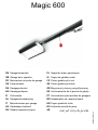
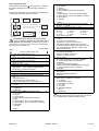
Magic 600
DE Garagentorantrieb PL Napęd do bram garażowych
GB Garage door operator SI Pogon za garažna vrata
FR Motorisation de porte de garage CZ Pohon garážových vrat
SE Portautomatik SK Pohon garážových brán
DK Garageportmotor GR Μηχανισμός κίνησης γκαραζόποτρας
NO Garasjeportåpner ES Accionamiento de la puerta de garaje
FI Ovikoneisto PT Automatismo para portões de garagem
NL Garagedeuraandrijving BG Задвижване на гаражна врата
IT Motorizzazione per garage HR Pogon garažnih vrata
HU Garázskapu-hajtómű RO Acţionare poartă de garaj
RU Привод гаражных ворот AE
ΕΎΟήΠϟ ΕΎΑϮΑ ϚϳήΤΗ ϡΎψϧ
N000924 12/2010


Magic 600 N000924 12/2010 I
Deutsch DE 1
English GB 8
Français FR 14
Svenska SE 21
Dansk DA 28
Norsk NO 34
Suomi FI 41
Nederlands NL 48
Italiano IT 55
Magyar HU 62
Русскии RU 69
Polski PL 77
Slovenščina SI 84
Ceština CZ 91
Slovensky SK 98
Ελληνικά GR 105
Español ES 113
Português PT 120
Български BG 127
Hrvatski HR 134
Română RO 141
AE 154
ǠȮȮŮǍȮȮŸ


Magic 600 N000924 12/2010 1 / 208
DE Deutsch
Original
Inhaltsverzeichnis
1 Einleitung 1
2 Produktbeschreibung 1
3 Symbolverwendung 1
4 Bestimmungsgemäße Verwendung, Garantie 1
5 Informelle Sicherheitsmaßnahmen 1
6 Sicherheitshinweise 1
7 Sicherheitshinweise für den Einbau 2
8 Sicherheitseinrichtungen des Torantriebes 2
9 Sicherheitsüberprüfung 2
Kraftabschaltung kontrollieren
Notentriegelung
Zusätzliche Sicherheitseinrichtungen
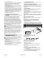
10 Anzeige- und Bedienelemente 2
11 Anschlüsse 2
12 Einbauvorbereitung 3
13 Montage 3
14 Inbetriebnahme 3
15 Torantrieb einlernen 3
Einlernen mit Handsender
Einlernen ohne Handsender
16 Handsender einlernen / löschen 3
17 Bedienung 4
18 Programmierung 4
19 Reset 5
20 Zusätzliche Sicherheitseinrichtungen anschließen 5
Lichtschranke
NOT-Stopp
21 Zusätzliche Anschlüsse 5
Zusatzbeleuchtung
Externer Impulseingang
Zusätzliche Antenne
22 Störungen beheben 5
Fehlerursachen / Abhilfe
Batterie des Handsenders wechseln
23 Wartungsintervalle 6
24 Konformitätserklärung 6
25 Technische Daten 7
26 Ersatzteile 7
27 Zubehör (optional) 7
28 Demontage, Entsorgung 7
Vor Einbau und Betrieb Betriebsanleitung sorgfältig lesen.
Abbildungen und Hinweise unbedingt beachten.
Der mitgelieferte Handsender ist auf den Torantrieb
eingelernt.
Verpackung: Es werden ausschließlich wieder verwertbare
Materialien verwendet. Verpackung entsprechend den
gesetzlichen Vorschriften und den Möglichkeiten vor Ort
umweltfreundlich entsorgen.
Lieferumfang siehe Seite 162.
In dieser Anleitung werden folgende Symbole verwendet:
VORSICHT Warnt vor einer Gefährdung von
Personen und Material. Eine Missachtung der mit
diesem Symbol gekennzeichneten Hinweise kann schwere
Verletzungen und Materialschäden zur Folge haben.
HINWEIS: Technische Hinweise, die besonders
beachtet werden müssen.
Dieser Torantrieb ist für die Nutzung an Privatgaragen
geeignet. Jeder darüber hinausgehende Gebrauch gilt als
nicht bestimmungsgemäß.
Ein Einsatz in explosionsgeschützter Umgebung ist
unzulässig.
Alle nicht durch eine ausdrückliche und schriftliche Freigabe
des Herstellers erfolgten
• Um- oder Anbauten
• Verwendungen von nicht originalen Ersatzteilen
• Durchführungen von Reparaturen durch nicht vom
Hersteller autorisierten Betrieben oder Personen
können zum Verlust der Gewährleistung führen.
Für Schäden, die
• aus der Nichtbeachtung der Betriebsanleitung resultieren
• auf technische Mängel am anzutreibenden Tor und
während der Benutzung auftretende Strukturverformungen
zurückzuführen sind
• aus unsachgemäßer Instandhaltung des Tores resultieren.
kann keine Haftung übernommen werden.
Betriebsanleitung für künftige Verwendung aufbewahren.
Das mitgelieferte Prüfbuch muss vom Montierenden
ausgefüllt werden und vom Betreiber mit allen anderen
Unterlagen (Tor, Torantrieb) aufbewahrt werden.
Allgemeine Sicherheitshinweise
Die Bedienung des Torantriebes darf nur erfolgen,
wenn der gesamte Bewegungsbereich frei einsehbar ist.
Beim Betätigen ist auf andere Personen im Wirkbereich zu
achten.
Arbeiten am Torantrieb nur bei stromlosem Antrieb
durchführen.
Unzulässige Tätigkeiten beim Betrieb eines Torantriebes:
• Hindurchgehen oder –fahren durch ein sich bewegendes
Tor.
• Heben von Gegenständen und / oder Personen mit dem
Tor.
• Kindern unbeaufsichtigt die Bedienung zu überlassen, sie
könnten damit spielen.
Ein Betrieb des Torantriebes darf nur erfolgen, wenn
• alle Benutzer in die Funktion und Bedienung eingewiesen
wurden.
• das Tor den Normen EN 12604, EN 12605 und DIN EN
13241-1 entspricht.
• die Torantriebsmontage normgerecht erfolgte (EN 12453,
EN 12445 und EN 12635).
• ggf. zusätzlich angebrachte Sicherheitseinrichtung
(Lichtschranke, Opto-Sensor, Sicherheitsleiste)
funktionstüchtig sind.
• bei Garagen ohne zweiten Zugang eine Notentriegelung
von außen vorhanden ist. Diese ist gegebenenfalls separat
zu bestellen.
• eine sich im Tor befindliche Schlupftür geschlossen und mit
einer Sicherheitseinrichtung versehen ist, die ein
Einschalten bei geöffneter Tür verhindert.
• vor Aktivierung der Schließautomatik eine zusätzliche
1 Einleitung
2 Produktbeschreibung
3 Symbolverwendung
4 Bestimmungsgemäße Verwendung,
Garantie
5 Informelle Sicherheitsmaßnahmen
6 Sicherheitshinweise

2 / 208 N000924 12/2010 Magic 600
Sicherheitseinrichtung (Sicherheitsleiste etc.) montiert
wurde.
• Bedienen Personen mit eingeschränkten physischen,
sensorischen oder geistigen Fähigkeiten oder mangels
Erfahrung und/oder mangels Wissen den Torantrieb,
müssen sie durch eine für Ihre Sicherheit zuständige
Person beaufsichtigt sein.
Einbau von geschultem Fachpersonal durchführen lassen.
Arbeiten an der Elektroinstallation dürfen nur durch
autorisiertes Fachpersonal durchgeführt werden.
Die Tragfähigkeit und Eignung der Stützkonstruktion des
Gebäudes, in die der Torantrieb eingebaut werden soll, ist
durch sachkundiges Personal zu überprüfen und zu
bestätigen.
Der Torantrieb muss an allen Befestigungspunkten sicher
und vollzählig befestigt werden. Die Befestigungsmaterialien
sind entsprechend der Beschaffenheit der Stützkonstruktion
so zu wählen, dass die Befestigungspunkte jeweils
mindestens einer Zugkraft von 900 N standhalten.
Werden diese Anforderungen nicht erfüllt, besteht die
Gefahr von Personen- und Sachschäden durch einen
herabstürzenden Antrieb oder ein sich unkontrolliert
bewegendes Tor.
Beim Bohren der Befestigungslöcher dürfen weder die Statik
des Gebäudes noch elektrische, wasserführende oder
andere Leitungen beschädigt werden.
Nach dem Hochheben des Torantriebes zur Gebäudedecke,
diesen bis zur vollständigen Befestigung mit geeigneten
Mitteln gegen Herunterfallen sichern. (Siehe Abbildung auf
Seite 159)
Einschlägige Arbeitsschutzvorschriften beachten, Kinder
während dem Einbau fernhalten.
Der Torantrieb verfügt über folgende
Sicherheitseinrichtungen. Diese dürfen weder entfernt
noch in Ihrer Funktion beeinträchtigt werden.
• Automatische Kraftabschaltung in den Funktionen „AUF“
und „ZU“
• Anschluss für Lichtschranke / Sicherheitsleiste / Opto-
Sensor.
• NOT-Stopp-Anschluss: Anschluss z.B. eines Schalters
(Optional) an einer im Tor eingebauten Schlupftüre.
• Notentriegelung (Siehe Seite 161 (J))
Kraftabschaltung kontrollieren
Die automatische Kraftabschaltung ist eine Einklemm- und
Schutzvorrichtung, die Verletzungen durch ein sich
bewegendes Tor verhindern soll.
Das Tor von außen mit beiden Händen in Hüfthöhe stoppen.
Beim Schließvorgang:
Das Tor muss automatisch halten und kurz zurücklaufen,
wenn es auf Widerstand stößt.
Beim Öffnungsvorgang:
Das Tor muss automatisch halten, wenn es auf Widerstand
stößt (Wenn Menue A7 = 1, erfolgt anschließend ein kurzer
Rücklauf).
Nach einer Kraftabschaltung blinkt die Torantriebsleuchte bis
zum nächsten Impuls oder Funk-Befehl.
Notentriegelung
Überprüfen gemäß den Angaben auf Seite 161 (J).
Zusätzliche Sicherheitseinrichtungen
Überprüfung auf einwandfreie Funktion gemäß den
Herstellerangaben.
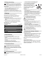
Meldungen der Leuchtanzeige (8)
7 Sicherheitshinweise für den Einbau
8 Sicherheitseinrichtungen des
Torantriebes
9 Sicherheitsüberprüfung
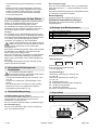
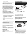
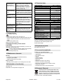
10 Anzeige- und Bedienelemente
5Taster Tor schließen / Minus
6Taster Menue / Bestätigung (Lernfahrt)
7Taster Tor öffnen / Plus
8 Leuchtanzeige
Statusmeldungen
A Tor in Endlage AUF
B Tor zwischen den beiden Endlagen
C Tor in Endlage ZU
Zustandsmeldungen
Während der Torbewegung in Richtung AUF:
C => B => A...
Während der Torbewegung in Richtung ZU:
A => B => C...
L4 Einstellen Endlage AUF
L3 Referenzfahrt ZU und Einstellen Endlage ZU
L2 Lernfahrt AUF (Kraftwerte)
L1 Lernfahrt ZU (Kraftwerte)
Err Fehler und Fehlernummer (blinkend)
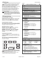
11 Anschlüsse
1 NOT-Stopp (grün)
2 Lichtschranke (gelb)
3 Impuls
567
8
A
B
C
132

Magic 600 N000924 12/2010 3 / 208
Wichtig: Tor auf Funktion sowie Leichtgängigkeit
prüfen und ggf. einstellen. Die Federspannung des
Tores muss so eingestellt sein, dass es ausbalanciert ist und
sich von Hand leicht, gleichmäßig und ruckfrei öffnen und
schließen lässt.
• Genormte und geeignete Schutzkontaktsteckdose ca. 10 -
50 cm neben Befestigungsposition Antriebskopf.
(Absicherung siehe technische Daten)
• Torantrieb nur in trockene Garagen einbauen.
Montagesatz für Toranschluss am zu montierenden Tortyp
bereithalten bzw. entsprechend dessen Anleitung montieren.
Siehe Hinweise zur Montage ab Seite 155.
Bei Bedarf kann der Antriebskopf um jeweils 90° zur
Laufschiene gedreht werden (Siehe Seite 155 (A)).
Montageschritt D, Seite 156:
1. Spannmutter des Zahnriemens anziehen bis Zahnriemen
nicht mehr in der Führungsschiene aufliegt (entspricht
Maß X).
2. Zahnriemenspannung mittels Spannmutter (Maß B)
entsprechend der Torantriebslänge (Maß A) erhöhen.
Montageschritt G, Seite 157, Einbaumaße:
Nach abgeschlossener Montage
• Tor von Hand langsam öffnen, bis Schlitten hörbar
einrastet.
• Netzanschluss herstellen, Display zeigt wechselnd
blinkend L und 4 an. Die Torantriebs-Lampe blinkt in 4-er-
Intervallen.
• Torantrieb einlernen (Siehe Kapitel 15)
• Handsender einlernen (Siehe Kapitel 16)
• Sicherheitsüberprüfung durchführen (Siehe Kapitel 9)
ACHTUNG: Beim Einlernen des Torantriebs
besteht kein Schutz durch Kraftabschaltung!
Hinweis: Einlernen nur bei Erstmontage oder nach einem
Reset des Torantriebs möglich. Während dem Lernvorgang
keine Tasten drücken.
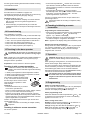
Vorbereitung: Tor am Torantrieb ankoppeln.
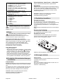
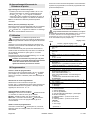
Einlernen mit Handsender
Der Handsender weist zum Zeitpunkt der Auslieferung
und nach einem Reset des Torantriebes folgende
Funktionen auf:
• A Totmann-Betrieb und Feineinstellung "AUF"
• B Totmann-Betrieb und Feineinstellung "ZU"
• C und D Bestätigung (Abspeichern)
Nach dem Einlernen des Torantriebs
wird Taste A zur Fernsteuerung
verwendet, die anderen Tasten können
zur Ansteuerung weiterer, baugleicher
Torantriebe oder Funkempfänger
eingesetzt werden.
Einlernen
• Taste A drücken und gedrückt halten, das Tor bewegt sich
in Öffnungsrichtung.
• Wenn gewünschte Position Endlage „AUF" erreicht ist,
Taste A loslassen. (Korrektur mit Taste B möglich)
• Taste C einmal kurz drücken, Lernvorgang: Der Torantrieb
lernt automatisch „Endlage AUF / ZU“ und Kräfte der
„Wege AUF / ZU“ ein. Torantriebsbeleuchtung blinkt
rhythmisch.
Der Lernvorgang ist abgeschlossen, wenn das Tor offen ist
und die Torantriebsbeleuchtung leuchtet.
Kraftabschaltung gemäß Kapitel 9,
Sicherheitsüberprüfung, überprüfen.
Einlernen ohne Handsender
Am Torantrieb:
• Taster drücken und gedrückt halten, das Tor bewegt
sich in Öffnungsrichtung. Taster loslassen, wenn
gewünschte Öffnungsposition erreicht ist. Eine Korrektur
ist mit Taster möglich.
• Taster Menue betätigen, Der Torantrieb lernt
automatisch „Endlage AUF / ZU“ und Kräfte der „Wege
AUF / ZU“ ein. Torantriebsbeleuchtung blinkt rhythmisch.
Der Lernvorgang ist abgeschlossen, wenn Tor offen ist und
die Torantriebsbeleuchtung leuchtet.
Kraftabschaltung gemäß Kapitel 9,
Sicherheitsüberprüfung, überprüfen.
Handsender einlernen:
• Während einer der 3 Statusmeldungen A, B oder C (Siehe
Kapitel 10) die Taster und gleichzeitig (ca. 1 Sek)
betätigen, im Display blinkt F.
• Die gewünschte Taste am Handsender betätigen, der
Funkbefehl ist eingelernt. Am Display wird F angezeigt.
Notiz: Während dem Sendeimpuls wird am Display F
angezeigt.
(Alle) Handsender löschen
Während einer der 3 Statusmeldungen A, B oder C (Siehe
Kapitel 10) die Taster und gleichzeitig >6 Sekunden
betätigen, im Display blinkt F. Nach 3 Sekunden erscheint
wieder die Statusmeldung.
12 Einbauvorbereitung
13 Montage
Deckensektionaltore
Abb.
Niedersturz Maß G
Euro 30 - 50mm G2
G60 20 - 40mm G3
G60 Max 30 - 50mm G1
Normalsturz
Euro 100 - 120mm G2
G60 100 - 120mm G3
G60 Max 100 - 120mm G1
Schwingtor 20 - 40mm G4
14 Inbetriebnahme
15 Torantrieb einlernen
16 Handsender einlernen / löschen

4 / 208 N000924 12/2010 Magic 600
VORSICHT: Sorgloser Umgang mit dem Torantrieb
kann zu Verletzungen oder Sachbeschädigungen
führen. Grundlegende Sicherheitsregeln beachten:
Beim Öffnen und Schließen des Tores die Schwenkbereiche
innen und außen freihalten. Kinder fernhalten.
Die Torbewegungen können über den mitgelieferten
Handsender oder optional anschließbare Schaltelemente
(z.B. Wandtaster) ausgelöst bzw. gestoppt werden.
Externe Zusatzeinrichtungen (z.B. NOT-Stopp) können
angeschlossen werden.
Der Antrieb darf nicht ohne angekoppeltes Tor
betrieben werden. Die Elektronik würde dadurch
falsche Kraftwerte einlernen. Funktionsstörungen
können die Folge sein.
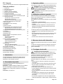
Programmier-Modus einschalten
Während einer der 3 Statusmeldungen A, B oder C (Siehe
Kapitel 10) Taster Menue länger als 1,5 Sekunden
betätigen. Die Anzeige wechselt zur Menüanzeige (D).
Programmier-Menue auswählen
Mit den Tastern und das gewünschte Menue auswählen.
Die 2-stellige Menuebezeichnung wird wechselnd blinkend
angezeigt. Für Menue A0 erscheint: A 0 A...
Menue-Wert anzeigen / verändern
Anzeigen: Taster Menue kürzer als 1,5 Sekunden
betätigen, der Menue-Wert (E) wird angezeigt.
Verändern: Mit den Tastern und Wert verändern.
Speichern: Taster Menue kürzer als 1,5 Sekunden
betätigen, das Programmier-Menue (D) wird wieder
angezeigt.
Programmiermodus verlassen
Taster Menue länger als 1,5 Sekunden betätigen, die
Anzeige wechselt zur Statusmeldung, Änderungen werden
gespeichert.
Wird während der Programmierphase innerhalb 15 Sek.
keine Taste gedrückt, wird der Programmiermodus
automatisch verlassen.
ACHTUNG: Werden die Werte der Programmier-
Menues A0 bis A4 verändert, besteht kein Schutz
mehr durch die Kraftabschaltung! Vor einer
Wiederinbetriebnahme Torantrieb neu einlernen. Dazu
Torantrieb einlernen (Kapitel 15) durchführen.
17 Bedienung
18 Programmierung
D
E
D
E
A
B
C
<1,5 Sek
>1,5 Sek
Werks-Einstellung
Menue
Funktion, Einstellbereich, Einheit
A0 Länge SOFTLAUF AUF in 7cm
0..9
2
A1 Länge SOFTLAUF ZU in 7cm
0..9
4
A2 Softlaufgeschwindigkeit (ZU) mm/Sek
0= 50...9= 140
5
A3 Backjump, AUS= 0 EIN= 1 1
A4 Laufrichtungswechsel, AUS= 0 EIN= 1
Einstellung (mit +/-) nur möglich wenn Stecker
NOT-STOPP (1, grün) ausgesteckt ist.
0
A5 Kraftzugabe AUF
1)
0..9 3
A6 Kraftzugabe ZU
1)
0..9 3
A7 Tortyp: Deckensektionaltor/Schwingtor = 0
Seitensektionaltor* = 1
Seitensektionaltor* mit Sanftanlauf = 2
* Hindernisfreigabe auch in Richtung AUF
0
A8 Vorwarnzeit (AUF/ZU) 1=2Sek... 8=16Sek 0
A9 Zusatzkarte
0= ZKMagicS
1= ZKMagic
0
b0 Relais 1 (bei Zusatzkarte ZKMagic)
0= keine Funktion
1= E-Schloss
2= Warnlicht *
3= Lichtschrankentest* (Unterbrechung
Senderspannung)
4= Zustandsanzeige*: Tor in Endlage AUF
5= Zustandsanzeige*: Tor in Endlage ZU
6= Grünampel*
7= Rotampel*
* wenn A9= 1
0
b1 Relais 2 (bei Zusatzkarte ZKMagic)
0= keine Funktion
1= E-Schloss*
2= Warnlicht *
3= Lichtschrankentest* (Unterbrechung
Senderspannung)
4= Zustandsanzeige*: Tor in Endlage AUF
5= Zustandsanzeige*: Tor in Endlage ZU
6= Grünampel*
7= Rotampel*
* wenn A9= 1
0
b2 Schließkantensicherung (Zusatzkarte)
0= AUS 1= OSE
0
b3 Leerfahrterkennung 0= AUS 1= EIN 1
b4
Schließautomatik
1)
0= AUS 1= 10 Sek 2= 30 Sek
3= 1 Min 4= 2 Min 5= 3 Min
6= 5 Min 7= 10 Min 9= 15 Min
Jeweils zuzgl. Vorwarnzeit
0
b6 Wartungsintervall*
0= AUS
1..9 (1000-Torbewegungen)
Beispiel: 5 = 5000 Torbewegungen
Nach Ablauf des Wartungsintervalls blinkt die
Antriebsbeleuchtung nach jedem Torlauf. Ein
Verstellen setzt den Zähler des Wartungsintervalls
zurück.
0
b7 Versionsnummer: 8 Ziffern werden zwei mal
nacheinander, mit führendem „-“, angezeigt.
Beispiel: -04200510 zeigt:
Version: 04 Datum: 20.05.10

Magic 600 N000924 12/2010 5 / 208
1)
Wird die Kraftzugabe (A5, A6) >3 und/oder die
Schließautomatik (b4) auf EIN (>0) eingestellt, darf
das Tor nur mit einer zusätzlichen Sicherheitseinrichtung
betrieben werden.
ACHTUNG: Nach dem Reset besteht kein Schutz
mehr durch Kraftabschaltung! Vor einer
Wiederinbetriebnahme Torantrieb neu einlernen. Dazu
Torantrieb einlernen (Kapitel 15) durchführen.
Reset (gespeicherte Werte der Lernfahrten)
Während einer der 3 Statusmeldungen A, B oder C (Siehe
Kapitel 10) gleichzeitig die Taster und Menue länger
als 8 und weniger als 10 Sekunden betätigen. Die
Leuchtanzeige blinkt (r), dann wird die Statusmeldung
angezeigt; der Reset ist durchgeführt.
Die Handsender werden nicht gelöscht.
Reset, Werkseinstellung
• Stecker (1) abziehen.
• Während einer der 3 Statusmeldungen A, B oder C (Siehe
10) gleichzeitig die Taster und Menue länger als 12
Sekunden betätigen. Die Leuchtanzeige blinkt zunächst
langsam, dann schneller (rES). Anschließend erscheint
wieder die Statusanzeige, der Reset ist durchgeführt.
Die unter Programmierung (Kapitel 18) dargestellten Werte
sind eingestellt. Die Handsender werden nicht gelöscht.
Lichtschranke
Funktion: Bei Betätigung des Sicherheitseinganges (Kontakt
wird geöffnet) stoppt der Antrieb und reversiert bis Endlage
AUF.
Ist zusätzlich die Funktion “Schließautomatik” aktiviert, fährt
der Antrieb nach der 3. in Folge auftretenden Hindernis-
Meldung in die Position Endlage AUF und schaltet ab.
Anschluss: Stecker mit gelber Brücke am externen
Anschluss 2 abziehen und aufbewahren.
Sicherheitseinrichtung anstecken.
Sicherheitsleiste, Opto-Sensor und Warnlicht
werden mittels Erweiterungsmodulen angeschlossen.
NOT-Stopp
Funktion: Wird die angeschlossene Sicherheitseinrichtung
während des Torzulaufes betätigt (Kontakt geöffnet), stoppt
das Tor sofort. Nach dem Schließen des NOT-Stopp-
Kontakts kann der Torantrieb mit dem nächsten Impuls
wieder bewegt werden.
Anschluss: Stecker mit grüner Brücke am externen
Anschluss 5, abziehen und aufbewahren.
Sicherheitseinrichtung anstecken.
Zusatzbeleuchtung
Der Anschluss darf nur durch eine Elektrofachkraft
durchgeführt werden. Zusätzlich zur Antriebsleuchte (40 W)
kann eine Zusatzbeleuchtung von max. 60 W (keine
Leuchtstoffröhre) an den Klemmen 1 und 2 angeschlossen
werden.
Notiz: Manche Energiesparlampen können das Funksignal
stören.
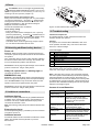
Externer Impulseingang
An den Klemmen 18 und 19 kann ein externes Impulssignal
(z.B. Wandtaster) angeschlossen werden.
Zusätzliche Antenne
An den Klemmen 21 und 20 (GND) kann eine externe
Antenne angeschlossen werden. Die interne Antenne
(Klemme 21) muss abgeklemmt werden.
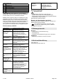
Abbildung: Steuerungsplatine. Siehe auch Seite 164.
Störfrequenzen
Funksignale anderer 433 MHz-Sender können sich auf den
Torantrieb störend auswirken.
Selbsttest
Nach dem Einschalten, jedem Motorlauf und alle 2.25 h im
Ruhebetrieb erfolgt ein Selbsttest.
Fehlerfrei = Statusmeldung.
b8 Service Modus
0= Bedienfeld frei, Menüpunkte verstellbar
0= Bedienfeld gesperrt, Menüpunkte nicht
verstellbar
0= Datenausgabe (Zusatzkarte)
Einstellung nur möglich, wenn Stecker NOT-
STOPP (1, grün) und Lichtschranke (2, gelb)
ausgesteckt ist.
0
b9 Fahrtenzähler: 8 Ziffern werden zwei mal
nacheinander, mit führendem „-“, angezeigt.
Beispiel: -00008000 zeigt:
8.000 Fahrten
C0 Testmodus für Magic-Door-Control (Option)
Funksignal, maximal 15 Sekunden:
0= kein Signal
1= Endlage AUF
2= Endlage ZU
3= Auflauf
4= Zulauf
5= Steht auf Strecke
7= Fehler
8= Hindernis
0
19 Reset
20 Zusätzliche Sicherheitseinrichtungen
anschließen
21 Zusätzliche Anschlüsse
22 Störungen beheben
1
2
21
20
19
18

6 / 208 N000924 12/2010 Magic 600
Fehlerbehebung: Reset (Kapitel 19) und anschließend
Arbeitsschritt Torantrieb einlernen (Kapitel 15) durchführen.
Tritt der Fehler erneut auf, Kundendienst anfordern.
Hinweis: Wird der gleiche Fehler bei 2 Selbsttests in Folge
festgestellt, erfolgt eine Verriegelung der Steuerung (Keine
Befehlsannahme). Nach ca. einer weiteren Minute erfolgt
erneut ein Selbsttest. Wird dann kein Fehler festgestellt, wird
Verriegelung wieder aufgehoben. Bleibt Fehler bestehen,
muss ein Reset durchgeführt werden. Alle Einstellungen sind
dann gelöscht. Der Torantrieb muss neu eingelernt werden.
Fehlerursachen / Abhilfe
Sicherung wechseln
Netzstecker ziehen.
• Antriebshaube demontieren, siehe Seite 164.
• Defekte Sicherung (S1) aus Sicherungshalter (S2)
herausziehen und auswechseln. Sicherungswert beachten!
• Antriebshaube wieder montieren.
Netzverbindung wieder herstellen.
Batterie des Handsenders wechseln
Gehäusedeckel öffnen. Batterie entnehmen, wechseln und
Gehäusedeckel wieder schließen.
Nur auslaufsichere Batterien verwenden. Beim
Einsetzen auf richtige Polung achten. Altbatterie
umweltgerecht entsorgen.
Monatlich
• Kraftabschaltung (Hindernissicherung)
• Notentriegelung
• Zusätzliche Sicherheitseinrichtungen (wenn vorhanden)
Halbjährlich
• Befestigung Torantrieb zur Decke und Wand.
Siehe Seite 165.
Einbauerklärung siehe Seite 166.
Fehlermeldungen*
2 EEprom-Daten
3 Strommessung
4 Hardware LS
5 Abschaltung Thyristoren
6 Abschaltung Relais
7 Watchdog-Test
8ROM-Test
9 RAM-Test
Beschreibung Mögliche Ursache / Abhilfe
Torantriebsleuchte
blinkt gleichmäßig
Tor ist auf Hindernis gefahren
Funktionstest durchführen
Torantriebsleuchte
blinkt in 4-er
Intervallen
Torantrieb ist nicht eingelernt,
Achtung, kein Schutz durch
Kraftabschaltung! Torantrieb
Torantrieb einlernen (Kapitel 15)
durchführen
Hindernissicherung
ohne Funktion
falsch eingestelltes Tor oder
Hindernis / Reset und neues
Einlernen durchführen
Antrieb läuft
überhaupt nicht
Keine oder falsche Stromversorgung
/ Sicherung Motorsteuerung defekt /
Externe Anschlüsse 7 und 8
überprüfen
Antrieb läuft
fehlerhaft
Schlitten nicht eingeklinkt /
Zahnriemen nicht gespannt /
Torschwelle vereist
Antrieb schließt das
Tor langsam
(Softlauf) während
Torantriebsleuchte
blinkt
Antrieb lernt selbstständig den
Arbeitsweg ein. Nach Endlage ZU
erfolgt automatisch Fahrt zur
Endlage AUF. Blinkt anschließend
Torantriebsleuchte in 4-er
Intervallen, Torantrieb einlernen
(Kapitel 15) durchführen
Antrieb schaltet
während dem Lauf
aus
Tor auf Leichtgängigkeit und
Hindernissicherung überprüfen /
Reset durchführen / Torantrieb
einlernen
Handsender ohne
Funktion, LED
leuchtet nicht
Batterie erneuern
Handsender ohne
Funktion
Wird während der Sender betätigt ist
am Display nicht die dem
Sendeimpuls zugeordnete
Funktionsmeldung (Siehe Kapitel
16) angezeigt: Handsender
einlernen / Schwacher Empfang
(Zusatzantenne installieren)
Energiesparlampen
Antrieb lässt sich
nicht über
Wandtaster (Option)
bedienen
Wandtaster und Steuerleitung prüfen
Antrieb lässt sich
nicht über
Handsender
bedienen
Funkpegel zu schwach. Störende
Funksignale aus anderen
Sendequellen liegen an /
Funkpegelkontrolle wie
nachstehend beschrieben
durchführen
23 Wartungsintervalle
24 Konformitätserklärung

Magic 600 N000924 12/2010 7 / 208
1) Durch äußere Störeinflüsse kann die Reichweite des
Handsenders unter Umständen erheblich reduziert sein.
2) Maßangabe bei gedrehtem Antriebskopf
3) zuzüglich Hubweg
Siehe Seite 162 und 163.
Im Fachhandel erhältlich:
• 4-Befehl-Handsender für Mehrfachnutzung
• Wandtaster
• Schlüsseltaster
•Codiertaster
• Funkcodiertaster
• Außenantenne
• Lichtschranke
• Erweiterungsmodul für Opto-Sensor
• Erweiterungsmodul für Warnlicht
• Notentriegelung von Außen oder Innen
• Sicherheitsleiste 8,2 KOhm
• potentialfreier Empfänger, verschiedene Frequenzen
Die Demontage des Torantriebes erfolgt in
umgekehrter Reihenfolge der Aufbauanleitung und
muss durch sachkundiges Personal erfolgen.
Die Entsorgung hat umweltgerecht zu erfolgen.
Elektrotechnische Teile dürfen nicht über den
Hausmüll entsorgt werden. 2002/96/EG(WEEE)
25 Technische Daten
Netzanschluss 230 V~, 50/60 Hz
Gerätesicherung 1,6 A, T (träge)
Leistungsaufnahme bei Nennlast 140 W
Ruhestrom < 2 W
Schutzart nur für trockene
Räume, IP 20
Schutzklasse 1
Funkfernsteuerung 433,92 MHz AM
Handsenderreichweite 1) 15 - 50 m
Handsender-Batterie CR 2032 (3V)
Leerlaufgeschwindigkeit ~ AUF >210 mm/s
~ ZU >140 mm/s
Anzugskraft 600 N
Nennlast 150 N
Hubweg
Magic 600 2890 +/- 25 mm
Magic 600 lang 3978 +/- 25 mm
Gesamtlänge 3) 615 +/- 25 mm
Gesamtlänge 2) 3) 485 +/- 25 mm
Breite 285 mm
Breite 2) 363 mm
Einbauhöhe Antriebsschiene 40 mm
Zulässige
Umgebungstemperaturen
-20 °C bis + 50 °C
Lagerung -20 °C bis + 80 °C
Beleuchtung E14, max. 40 W
Maximale Anzahl Betriebsspiele
pro Stunde bei Nennlast
20
Maximale Anzahl Betriebsspiele
ohne Pause bei Nennlast
8
Schallpegel, in 2m Abstand ≤69 dB(A)
26 Ersatzteile
27 Zubehör (optional)
28 Demontage, Entsorgung

8 / 208 N000924 12/2010 Magic 600
GB English
Translation of the German original operating manual
Table of contents
1 Introduction 8
2 Product description 8
3 Symbols 8
4 Intended usage, Guarantee 8
5 Informal Safety Measures 8
6 Safety instructions 8
7 Installation precautions 9
8 Safety devices of the door operator 9
9 Safety inspection 9
Checking load switch-off
Emergency release
Additional safety devices
10 Controls and indicators 9
11 Connections 9
12 Installation preparations 9
13 Installation 10
14 Commissioning 10
15 Teaching in the door operator 10
Teaching in with a remote transmitter
Teaching in without a remote transmitter
16 Teaching in/deleting a remote transmitter 10
17 Operation 10
18 Programming 10
19 Reset 12
20 Attaching additional safety devices 12
Photo cell
EMERGENCY stop
21 Additional connections 12
Additional lighting
External pulse input
Additional antenna
22 Troubleshooting 12
Causes of errors/Remedies
Changing the battery of the remote transmitter
23 Maintenance intervals 13
24 Declaration of conformity 13
25 Technical data 13
26 Replacement parts 13
27 Accessories (optional) 13
28 Removal, Disposal 13
Read operating instructions carefully before installing and
commissioning. Pay attention to the illustrations and all notes.
The remote transmitter supplied is taught in to the door
operator.
Packaging: Only reusable materials are used. Dispose of
packaging in an environmentally-friendly way and according
to local legal guidelines.
Scope of delivery see page 162
The following symbols are used in this manual:
CAUTION Warns of potential injury and material
damage. Non-observance of instructions marked with
these symbols can result in serious injuries and material
damage.
NOTE: Important technical instructions that must be
observed.
This door operator is suitable for use in domestic garages.
Any other use is deemed incorrect.
This product must not be used in explosion-protected
atmospheres.
The manufacturer must provide written and express approval
for:
• Modifications or attachments
• Use of parts other than factory authorised replacement
parts
• Repairs performed by persons or businesses that have not
been authorised by the manufacturer.
If approval is not obtained for any of the above, this may
invalidate the product’s guarantee.
We will not be liable for damage
• Due to non-compliance with operating instructions
• Due to technical errors in connecting the door operator and
structural deformations that may occur during operation
• As a result of inappropriate door maintenance.
door maintenance.
Keep the operating instructions handy for future use.
The inspection and testing log book provided must be filled
out by the person carrying out the installation and kept by the
operator along with all other documentation (door, door
operator).
General safety instructions
The door operator may only be used if the entire range
of motion is clearly visible. Be mindful of others within the
action range of this product during operation.
Always disconnect the electrical power before working on the
door operator.
Actions prohibited during use of a door operator:
• Passing or driving underneath a moving door
• Lifting of objects and/or persons with the door
• Children must not be left to operate the product
unsupervised; it is not a toy.
The door must only be operated when
• all users are familiar with its functions and operation.
• the door meets the requirements of European standards
EN 12604, EN 12605 and DIN EN 13241-1.
• the door operator is installed in compliance with the
relevant standards (EN 12453, EN 12445 and EN 12635).
• any optional safety devices such as a photo cell,
optosensor or safety rail are fully functional.
• garages without a second entrance have an emergency
lock release from the outside. It may be ordered separately
if necessary.
• an inset door in the garage door is closed and is equipped
with a safety device that prevents activation when the door
is open.
• an additional safety device (safety rail, etc.) has been
installed prior to activation of the automatic closure
function.
• If a person with restricted physical, sensory or mental
capacity, or a person with little experience and/or
knowledge of the door operator is to use the device, they
1 Introduction
2 Product description
3 Symbols
4 Intended usage, Guarantee
5 Informal Safety Measures
6 Safety instructions

Magic 600 N000924 12/2010 9 / 208
must be supervised by a person who assumes
responsibility for their safety.
Installation must be performed by qualified service
technician.
Work on the electrical installation must only be carried out by
authorised specialist personnel.
The load capacity and suitability of the supporting
construction of the building in which the door operator is to be
installed must be inspected and approved by an expert.
The door operator must be fully and securely attached at all
fastening points. All fastening materials must be selected
according to the nature of the supporting construction and
they must be able to withstand traction force of 900 N.
In the event of non-conformance with these
requirements, there is a risk of injury and material
damage caused by a falling operator or an uncontrolled
movement of the door.
When drilling the fastening holes, do not damage the building
structure or any electrical, water or other lines.
After lifting up the door operator to the ceiling, fasten it fully
with appropriate tools to prevent it from falling down. See
illustration on page 159.
Please observe appropriate industrial safety regulations and
keep children away during installation.
The door operator has the following safety devices. Do
not remove them or alter their functionality.
• Automatic load switch-off during functions "OPEN" and
"CLOSE"
• Connection for photo cell / safety rail / optosensor
• EMERGENCY stop connection: Connection of a switch
(optional) to an inset door mounted in the garage door, for
example
• Emergency release (see page 161 (J))
Checking load switch-off
The automatic load switch-off is a clamping and safety
mechanism that is designed to prevent accidents due to a
moving door.
Stop the door from outside with both hands at waist height.
When closing:
The door must stop automatically and reverse a little if it
comes into contact with an obstruction.
When opening:
The door must stop automatically when it meets with
resistance (if menu A7 = 1, it moves back a short distance).
After load switch-off, the door operator lights flash until the
next pulse or wireless command is received.
Emergency release
Check as per the information provided on page 161 (J).
Additional safety devices
Check for proper functioning as per the manufacturer’s
instructions.
Messages of the indicator lamp (8)
Please note: Check that the door is working properly
and running smoothly, and adjust if necessary. The
spring tension of the door must be set in such a way that it is
stable and can be opened and closed by hand smoothly and
without jolting.
• Standard and appropriate shock-proof socket approx. 10 -
50 cm away from the fastening position for the head of the
operator.
(For information on fuses, see the technical data.)
• Only install the door operator in dry garages.
Make sure the installation set for the connection is ready on
7 Installation precautions
8 Safety devices of the door operator
9 Safety inspection
10 Controls and indicators
5 Pushbutton Close door / Minus
6 Pushbutton Menu / Confirm (Teach-in run)
7 Pushbutton Open door / Plus
8 Indicator lamp
Status messages
A door in end position OPEN
B door between the two end positions
C door in end position CLOSED
Status messages
During door movement in OPEN direction
C => B => A...
During door movement in CLOSE direction
A => B => C...
L4 Set end position OPEN
L3 Reference run CLOSE and set end position CLOSED
L2 Teach-in run OPEN (load values)
L1 Teach-in run CLOSE (load values)
Err Error and error number (flashing)
11 Connections
1 EMERGENCY stop (green)
2 Photo cell (yellow)
3Pulse
12 Installation preparations
567
8
A
B
C
132

10 / 208 N000924 12/2010 Magic 600
the door type that is being attached and/or install it according
to the relevant manual.
See instructions for installation on page ff 155.
The head of the operator can be turned by 90° to the running
rail respectively as required (see page 155 (A)).
Installation step D, page 156:
1. Tighten the toothed belt’s clamping nut until the toothed
belt no longer rests on the guide rail (equivalent to
dimension X).
2. Use the clamping nut (dimension B) to increase the
toothed belt tension to correspond to the length of the door
operator.
Once installation is complete
• Slowly open the door by hand until you hear the slide snap
in.
• Make connection to mains, display flashes alternately with
L and 4. The door operator lamp flashes in intervals of 4.
• Teach in the door operator (see Chapter 15).
• Teach in the remote transmitter (see Chapter 16).
• Carry out a safety inspection (see Chapter 9).
ATTENTION: No protection is provided by the load
switch-off whilst the door operator is being taught
in.
Note: Teaching in is only possible during initial installation or
after resetting the door operator. Do not press any keys
during the teach-in procedure.
Preparation: Connect the door to the door operator.
Teaching in with a remote transmitter
At the time of delivery and after resetting the door
operator, the remote transmitter supports the following
functions:
• A Safety control operation and fine adjustment "OPEN"
• B Safety control operation and fine adjustment "CLOSE"
• C and D Confirmation (storage)
Once the door operator has been taught
in, key A is used for remote control and
the other keys can be used to control
other similar door operators or other
radio receivers.
Teaching in
• Press and hold down key A; the door
moves in the open direction.
• When you reach the desired end position "OPEN", release
key A. (You can make corrections with key B.)
• Press key C once briefly, teach-in procedure: The door
operator automatically stores "End position OPEN/CLOSE"
and the loads of the "Travel path OPEN/CLOSE". The door
operator lights flash in synchronism.
Teach-in is complete when the door is open and the door
operator lights are on.
Check load switch-off according to Chapter 9,Safety
inspection.
Teaching in without a remote transmitter
On the door operator:
• Press and hold pushbutton and the door moves in the
open direction. Release pushbutton when the desired
opening position is reached. A correction can be made with
the pushbutton .
• Press the Menu pushbutton The door operator
automatically stores "End position OPEN/CLOSE" and the
loads of the "Travel path OPEN/CLOSE" . The door
operator lights flash in synchronism.
Teach-in is complete when the door is open and the door
operator lights are on.
Check load switch-off according to Chapter 9,Safety
inspection.
Programming the remote transmitter:
• During one of the 3 status messages A, B or C (seeChapter
10), press the pushbuttons and simultaneously
(approx. 1 s), F flashes in the display.
• Press the desired key on the remote transmitter, the radio
command is taught in. F appears in the display.
Note: F appears in the display during the transmission pulse.
Deleting (all) remote transmitter(s):
During one of the 3 status messages A, B or C (see Chapter
10), press the pushbuttons and simultaneously for >6
seconds, F flashes in the display. The status message
reappears after 3 seconds.
CAUTION: Mishandling the product can result in
injuries or material damage. Follow the basic safety
rules:
When opening or closing the door, do not block the interior or
exterior swivel ranges. Keep children away.
The door movements can be activated or stopped using the
remote transmitter provided or via switching elements such
as the wall keypad, which can be connected if desired.
Optional external features (such as the EMERGENCY STOP)
can also be connected to the door operator.
The operator must be connected to a door before
it is used. If it is not, incorrect load values will be
taught in to the electronic system. This can cause
malfunctions.
Switch on programming mode
During one of the 3 status messages A, B or C (seeChapter
10) press the Menu pusbutton for longer than 1.5
seconds. The display changes to the menu (D).
Select programming menu
Select the desired menu with the pushbuttons and . The
2-character menu name flashes on and off. The following
appears for menu A0: A 0 A...
Show / change menu value
Displays: Press the Menu pushbutton for less than 1.5
seconds, the menu value (E) is displayed.
Change: Change the value with the pushbuttons and .
Save: Press the Menu pushbutton for less than 1.5
seconds, the programming menu (D) is displayed.
13 Installation
14 Commissioning
15 Teaching in the door operator
16 Teaching in/deleting a remote
transmitter
17 Operation
18 Programming

Magic 600 N000924 12/2010 11 / 208
Exit programming mode
Press the Menu pushbutton for longer than 1.5 seconds,
the display changes to the status message, changes are
saved.
If no key is pressed within 15 seconds during programming, it
automatically exits the programming mode.
ATTENTION: If the values of the programming
menu A0 to A4 are changed, the load switch-off no
longer provides any protection! Teach the door operator in
again before re-commissioning. For this carry out Teaching in
the door operator (Chapter 15) .
1)
If the added load (A5, A6) is >3 and/or the automatic
closing (b4) is set to ON (>0), the door may only be
operated with an additional safety device.
Factory setting
Menu
Function, setting range, unit
A0 Length SOFT RUN OPEN in 7cm
0..9
2
A1 Length SOFT RUN CLOSE in 7cm
0..9
4
A2 Soft running speed (CLOSE) mm/s
0= 50...9= 140
5
A3 Backjump, OFF= 0 ON= 1 1
A4 Change in direction, OFF= 0 ON= 1
Setting (with +/-) only possible if EMERGENCY
STOP plug (1, green) is unplugged.
0
A5 Added load
1)
OPEN 0..9 3
A6 Added load
1)
CLOSE 0..9 3
A7 Door type: Overhead sectional door/one-piece
door = 0
Side sectional door* = 1
Side sectional door with soft start = 2
* Obstruction release also in OPEN direction
0
A8 Warning time (OPEN/CLOSE) 1=2secs...
8=16secs
0
A9 Accessory card
0= ZKMagicS
1= ZKMagic
0
b0 Relay 1 (with ZKMagic accessory card)
0= no function
1= E-lock
2= warning light *
3= photo cell test* (interruption transmitter
voltage)
4= status display*: Door in end position OPEN
5= status display*: Door in end position CLOSED
6= green light*
7= red light*
* if A9= 1
0
D
E
D
E
A
B
C
<1,5 Sek
>1,5 Sek
b1 Relay 2 (with ZKMagic accessory card)
0= no function
1= E-lock*
2= warning light *
3= photo cell test* (interruption transmitter
voltage)
4= status display*: Door in end position OPEN
5= status display*: Door in end position CLOSED
6= green light*
7= red light*
* if A9= 1
0
b2 Closing edge protection (accessory module)
0= OFF 1= OSE
0
b3 Empty run detection 0= OFF 1= ON 1
b4 Automatic closure function
1)
0= OFF 1= 10 secs 2= 30 secs
3= 1 min 4= 2 min 5= 3 min
6= 5 min 7= 10 min 9= 15 min
resp. plus warning time
0
b6 Maintenance interval*
0= OFF
1..9 (1,000 door movements)
Example: 5 = 5,000 door movements
The operator lighting flashes after every door
movement when the maintenance interval has run
out. A misadjustment resets the counter of the
maintenance interval.
0
b7 Version number: 8 digits are displayed twice in
succession with leading “-“.
Example: -04200510 indicates:
Version: 04 Date: 20.05.10
b8 Service mode
0= control panel free, menu items adjustable
0= control panel locked, menu items not
adjustable
0= data output (accessory card)
Setting only possible if EMERGENCY STOP plug
(1, green) and photo cell (2, yellow) are
unplugged.
0
b9 Run counter: 8 digits are displayed twice in succession
with leading “-“.
Example: -00008000 indicates:
8,000 runs
C0 Test mode for Magic-Door-Control (option)
Radio signal, maximum 15 seconds:
0= no signal
1= end position OPEN
2= end position CLOSED
3= run open
4= run close
5= standstill underway
7= error
8= obstruction
0

12 / 208 N000924 12/2010 Magic 600
ATTENTION: Ther is no longer any protection by
switching off the load after the reset. Teach the door
operator in again before re-commissioning. For this carry out
Teaching in the door operator (Chapter 15) .
Reset (saved values of the teach-in runs)
During one of the 3 status messages A, B or C (see Chapter
10) press the pushbuttons and Menu simultaneously
for longer than 8 seconds and less than 10 seconds. The
indicator lamp flashes (r), then the status message is
displayed; the reset is carried out.
The remote transmitters are not deleted.
Reset, factory setting
• Pull out the plug (1).
• During one of the 3 status messages A, B or C (see 10)
press the pushbuttons and Menu simultaneously for
longer than 12 seconds. The indicator lamp flashes slowly
at first, then quicker (rES). Then the status display
reappears, the reset is made.
The values shown under Programming (Chapter 18) are
set. The remote transmitters are not reset.
Photo cell
Function: When the safety input is activated (opening the
contact) the operator stops and reverses as far as the OPEN
end position.
If the “automatic closure” function is also activated, following
the third successive obstruction message, the operator will
move to the OPEN end position and shut down.
Connection: Pull out plug with yellow bridge on the external
junction 2 and store it. Plug on safety device.
Safety rail, opto-sensor and warning light are
connected by extension modules.
EMERGENCY stop
Function: If the external safety device is operated when the
door is moving (Contact opened), the door stops immediately.
Once the EMERGENCY stop contact has closed, the door
operator can be moved again with the next pulse.
Connection: Pull out plug with green bridge on the external
junction 5 and store it. Plug on safety device.
Additional lighting
Connection must be performed only by qualified electricians.
In addition to the operator light (40W), optional lighting of a
maximum of 60 W (no tubular fluorescent lamps) can be
connected to terminals 1 and 2.
Note: Some energy saving lamps can interfere with the radio
signal.
External pulse input
An external pulse signal (e.g. wall button) can be connected
to terminals 18 and 19.
Additional antenna
An external antenna can be connected to terminals 21 and 20
(GND). The internal antenna (terminal 21) must be
disconnected.
Figure: Control board See also page 164.
Interference frequencies
The wireless signals of other 433 MHz transmitters can
interfere with the door operator.
Self-test
The system runs a self-test after initialisation, after each
motor operation and after every 2.25 hours in idle mode.
Error free = status message.
Troubleshooting: Reset (Chapter 19) and then perform work
step Teaching in the door operator (Chapter 15)
If the error occurs again, request customer service.
Note: If the same error occurs in two successive self-tests,
the control system will be disabled (commands are rejected).
After approximately one further minute, the system runs
another self-test. If no errors are detected, the control system
is enabled again. If the error persists, a reset will need to be
performed. This will delete all settings and the door operator
will have to be taught in again.
Causes of errors/Remedies
19 Reset
20 Attaching additional safety devices
21 Additional connections
22 Troubleshooting
Error messages*
2 EEprom data
3 Current measurement
4 Hardware Photo cell
5 Switch off thyristors
6 Switch off relay
7 Watchdog test
8 ROM test
9RAM test
Description Possible cause/Remedy
Door operator light
flashes evenly
The door has hit an obstruction, do
function test
Door operator light
flashes at intervals of
4
Door operator is not taught in,
attention no protection by load
switch-off! Carry out door operator
Teaching in the door operator
(Chapter 15)
Entrapment
protection device not
working.
Incorrect setting of door or
entrapment protection device /
Reset and teach in again
The operator is not
working at all.
None or wrong voltage supply / The
fuse of the motor control is defective
/ Check external terminals 7 and 8.
The operator is
defective.
The slides are not snapped-in
properly./The toothed belts are not
tensioned correctly./The door
thresholds are frozen.
1
2
21
20
19
18

Magic 600 N000924 12/2010 13 / 208
Changing the fuse
Pull out mains plug.
• Remove the operator hood, see page 164.
• Remove the faulty fuse (S1) from the fuse holder (S2) and
replace it. Make sure that the new fuse has the correct
value!
• Replace the operator hood.
Restore the mains connection.
Changing the battery of the remote
transmitter
Open the housing cover. Remove the battery, fit a new one
and replace the housing cover.
Use only leak-proof batteries. Make sure the polarity
is correct. Dispose of used batteries in an
environmentally-friendly way.
Monthly
• Load switch-off (entrapment protection device)
• Emergency lock release
• Additional safety devices (if fitted)
Every 6 months
• Mounting of door operator on the ceiling and on the wall
See page 167.
Declaration of incorporation see page 168.
1) The transmission range of the remote transmitter may be
reduced considerably by external interference.
2) Dimensions with turned operator head
3) plus stroke length
See pages 162 and 163.
Available from specialised dealer's:
• 4-command multi-use remote transmitter
• Wall keypad
• Key-operated control
• Keypad
• Wireless keypad
• External antenna
• Photo cell
• Extension module for opto-sensor
• Extension module for warning light
• Emergency lock release from outside or inside
• Safety rail 8.2 kohms
• Potential-free receiver, various frequencies
Removing the door operator takes place in the
reverse sequence of the installation instructions
and must be carried out by qualified technicians.
Dispose of the device according to environmental
guidelines. Electrical parts must not be disposed of
as domestic waste. 2002/96/EG (WEEE)
Operator closes the
door slowly (soft
start) whilst door
operator light flashes
Operator teaches in the travel
automatically. After CLOSED end
position, moves automatically to
OPEN end position. If the door
operator light flashes in intervals of
4, carry outTeaching in the door
operator (Chapter 15)
The operator
switches off during
motion.
Check that the door is running
smoothly and that the entrapment
protection device is working properly
/ Reset / Teach in the door operator
Remote transmitter is
not working, LED not
alight
Replace the batteries
Remote transmitter is
not working
If the function message assigned to
the transmission pulse is not
displayed whilst the transmitter is
actuated (see Chapter 16): Teach in
remote transmitter / Poor reception
(install optional antenna) energy-
saving lamps
The operator cannot
be used via the wall
keypad (optional).
Check the wall keypad and control
wire.
The operator cannot
be used via the
remote transmitter
(optional).
Radio level too weak. There are
interfering radio signals from other
transmission sources / Carry out
radio level check as described below
23 Maintenance intervals
24 Declaration of conformity
25 Technical data
Mains connection 230 V~, 50/60 Hz
Device fuse 1.6 A, T (slow-blow)
Power consumption at rated load 140 W
Closed current < 2 W
Degree of protection For dry rooms
only, IP 20
Protection class 1
Wireless remote control 433.92 MHz AM
Remote transmitter range 1) 15 - 50 m
Remote transmitter batteries CR 2032 (3 V)
Idle speed ~ OPEN >210 mm/s
~ CLOSE >140 mm/s
Traction 600 N
Rated load 150 N
Stroke length
Magic 600 2890 +/- 25 mm
Magic 600 long 3978 +/- 25 mm
Total length 3) 615 +/- 25 mm
Total length 2) 3) 485 +/- 25 mm
Width 285 mm
Width 2) 363 mm
Installation height drive rail 40 mm
Permissible
ambient temperatures
-20°C to 50 °C
Storage -20°C to 80 °C
Lighting E14, max. 40 W
Maximum number of duty cycles
per hour at rated load
20
Maximum number of duty cycles
without a break at rated load
8
Noise level at a distance of 2 m ≤69 dB(A)
26 Replacement parts
27 Accessories (optional)
28 Removal, Disposal

14 / 208 N000924 12/2010 Magic 600
FR Français
Traduction des instructions de service originales allemandes
Table des matières
1 Introduction 14
2 Description du produit 14
3 Symboles utilisés 14
4 Utilisation conforme, garantie 14
5 Mesures de sécurité informelles 14
6 Consignes de sécurité 14
7 Consignes de sécurité pour le montage 15
8 Dispositifs de sécurité de la motorisation de porte 15
9 Contrôle de sécurité 15
Contrôle de la coupure de sécurité
Déverrouillage de secours
Dispositifs de sécurité supplémentaires
10 Eléments d'affichage et de commande 15
11 Branchements 16
12 Préparations pour le montage 16
13 Montage 16
14 Mise en service 16
15 Apprentissage de la motorisation de porte 16
Apprentissage avec émetteur de poche
Apprentissage sans émetteur de poche
16 Apprentissage/effacement de l’émetteur de poche 17
17 Utilisation 17
18 Programmation 17
19 Remise à zéro 18
20 Raccordement de dispositifs de sécurité
supplémentaires 18
Cellule photoélectrique
Arrêt d’urgence
21 Raccordements supplémentaires 18
Eclairage supplémentaire
Entrée d'impulsions externe
Antenne supplémentaire
22 Dépannage 19
Causes de défauts/Remèdes
Remplacement de la pile de l’émetteur de poche
23 Intervalles d’entretien 20
24 Déclaration de conformité 20
25 Caractéristiques techniques 20
26 Pièces de rechange 20
27 Accessoires (en option) 20
28 Démontage, élimination 20
Lire attentivement les instructions de service avant le
montage et l’utilisation. Observer impérativement les
illustrations et les indications fournies.
L'émetteur de poche fourni est programmé pour la
motorisation de porte.
Emballage : Toutes les matières utilisées sont recyclables.
Eliminer l’emballage en respectant l’environnement,
conformément aux dispositions légales et aux possibilités
locales.
Fournitures, voir page 162.
Les symboles ci-après sont utilisés dans la présente notice :
PRUDENCE Signale un danger pour les personnes et
le matériel. La non-observation des indications
signalées par ce symbole peut être à l’origine de blessures
graves et de dommages matériels.
REMARQUE : Informations techniques à observer
plus particulièrement.
Cette motorisation de porte est conçue pour les garages
privés. Toute utilisation sortant de ce cadre est considérée
comme étant non conforme.
Son utilisation en environnement explosif n’est pas autorisée.
Toutes
• modifications ou transformations
• utilisations de pièces de rechange autres que des pièces
d’origine
• réparations par des entreprises ou des personnes non
agréées par le fabricant peuvent entraîner la perte des
prestations de garantie.
Le fabricant décline toute responsabilité pour les dommages
• consécutifs à la non-observation des instructions de
service
• dus à des défauts techniques de la porte motorisée et à des
déformations de la structure intervenues au cours de
l’utilisation
• résultant d’une maintenance incorrecte de la porte.
.
Conserver les instructions de service en vue d’une utilisation
future.
Le cahier de contrôle joint doit être rempli par le monteur et
conservé par l’utilisateur avec tous les autres documents
(porte, motorisation).
Consignes de sécurité générales
La motorisation de porte ne doit être utilisée que si
l’intégralité de la zone de déplacement de la porte est visible.
Lorsque la motorisation est actionnée, s’assurer que
personne ne se trouve dans le rayon d’action.
Le courant de la motorisation doit être coupé avant
l’exécution de travaux sur celle-ci.
Activités interdites lors de l’utilisation d’une motorisation de
porte :
• Passer à pied ou à bord d’un véhicule sous la porte en
mouvement.
• Lever des objets et/ou des personnes à l’aide de la porte.
• Ne pas confier la commande à des enfants pour éviter
qu’ils ne jouent avec celle-ci.
La motorisation de porte ne peut être utilisée que si
• tous les utilisateurs ont été informés de son fonctionnement
et de son utilisation.
• la porte satisfait aux normes EN 12604, EN 12605 et DIN
EN 13241-1.
• le montage de la motorisation de porte a été effectué
conformément aux normes (EN 12453, EN 12445 et
EN 12635).
• les éventuels équipements de sécurité supplémentaires
(cellule photoélectrique, capteur optique, listel de sécurité)
1 Introduction
2 Description du produit
3 Symboles utilisés
4 Utilisation conforme, garantie
5 Mesures de sécurité informelles
6 Consignes de sécurité

Magic 600 N000924 12/2010 15 / 208
sont en ordre de marche.
• un déverrouillage de secours accessible depuis l’extérieur
est prévu pour les garages qui ne disposent pas d’un
deuxième accès. Le cas échéant, celui-ci doit être
commandé séparément.
• un portillon équipant la porte de garage est fermé et muni
d’un dispositif de sécurité empêchant la mise en marche
lorsque le portillon est ouvert.
• un dispositif de sécurité supplémentaire (listel de sécurité,
etc.) a été monté avant d'activer la fermeture automatique.
• Les personnes, dont les facultés physiques, sensorielles
ou mentales sont déficientes ou dont l'expérience et/ou les
connaissances sur la motorisation de porte sont
insuffisantes, doivent être supervisées par une personne
responsable de leur sécurité.
Le montage doit être confié à un personnel qualifié.
Les travaux sur l’installation électrique ne doivent être
effectués que par un personnel qualifié et agréé.
La charge admissible et l’adéquation de la structure du
bâtiment qui doit recevoir la motorisation de porte doivent
être vérifiées et confirmées par un professionnel qualifié.
La motorisation de porte complète doit être fixée de manière
sûre à tous les points de fixation. Le matériel de fixation doit
être choisi en fonction de la structure support de manière à ce
que les points de fixation acceptent chacun une force de
traction minimale de 900 N.
Si ces critères ne sont pas remplis, un risque de
dommage corporel et matériel existe en cas de chute
de la motorisation ou de mouvement incontrôlé de la porte.
Le perçage des trous de fixation ne doit endommager ni la
statique du bâtiment, ni des conducteurs électriques ou des
conduites d’eau ou autres.
Après avoir soulevé la motorisation au plafond du bâtiment,
l’empêcher de tomber à l’aide de moyens appropriés jusqu’à
sa fixation complète. (Voir l’illustration de la page 159)
Observer les consignes de sécurité au travail en vigueur,
éloigner les enfants pendant les travaux.
La motorisation de porte possède les dispositifs de
sécurité ci-après. Ceux-ci ne doivent pas être retirés et
leur fonctionnement ne doit pas être entravé.
• Coupure automatique de sécurité en «OUVERTURE» et
«FERMETURE»
• Raccordement pour cellule photoélectrique/listel de
sécurité/capteur optique.
• Raccordement d’arrêt d’urgence: pour le raccordement par
ex. d’un interrupteur (en option) sur un portillon intégré
dans la porte de garage.
• Déverrouillage de secours (voir page 161 (J))
Contrôle de la coupure de sécurité
La coupure de sécurité automatique est un dispositif destiné
à prévenir les blessures dues au déplacement de la porte.
Arrêter la porte de l’extérieur avec les deux mains, à hauteur
des hanches.
Lors de la fermeture:
Lorsqu'elle rencontre une résistance, la porte doit s’arrêter
automatiquement et repartir légèrement en arrière.
Lors de l'ouverture:
La porte doit s'arrêter automatiquement si elle rencontre une
résistance (si le menu A7 = 1, une brève marche arrière se
produit ensuite).
Après une coupure de sécurité, la lampe de la motorisation
de porte clignote jusqu’à la prochaine impulsion ou instruction
radio.
Déverrouillage de secours
Effectuer les vérifications selon les indications fournies à la
page 161 (J).
Dispositifs de sécurité supplémentaires
Vérifier le parfait fonctionnement conformément aux
indications du fabricant.
Messages des témoins lumineux (8)
7 Consignes de sécurité pour le
montage
8 Dispositifs de sécurité de la
motorisation de porte
9 Contrôle de sécurité
10 Eléments d'affichage et de commande
5 Touche Fermer porte/Moins
6 Touche Menu/Confirmation (course d'apprentissage)
7 Touche Ouvrir porte/Plus
8 Témoin lumineux
Messages d'état
A Porte en fin de course OUVERTE
B Porte entre les deux fins de course
C Porte en fin de course FERMEE
Messages de situation
Lors du mouvement de la porte dans le sens OUVERT:
C => B => A...
Lors du mouvement de la porte dans le sens FERME:
A => B => C...
L4 Réglage de la fin de course OUVERT
L3 Course de référence FERME et réglage de la fin de
course FERME
L2 Course d'apprentissage OUVERT (valeurs de force)
L1 Course d'apprentissage FERME (valeurs de force)
Err Erreur et numéro de l'erreur (clignotant)
567
8
A
B
C

16 / 208 N000924 12/2010 Magic 600
Important : vérifier le fonctionnement et la bonne
mobilité de la porte. La régler si nécessaire. La
tension des ressorts de la porte doit être ajustée de manière
à ce que le porte soit équilibrée et que l'ouverture et la
fermeture manuelles se fassent facilement, régulièrement et
sans à-coups.
• Prise de courant avec contact de protection normalisée
adaptée à env. 10 à 50 cm de la position de fixation du
bouton de la motorisation.
(Fusibles, voir les caractéristiques techniques).
• La motorisation de porte ne doit être montée que dans des
garages secs.
Préparer le kit de montage pour le raccordement de la porte
et le monter conformément à la notice.
Voir les Indications de montage, à partir de la page 155.
Au besoin, la tête d'entraînement peut être pivotée de 90º par
rapport au rail de roulement (voir page 155 (A)).
Etape de montage D, page 156:
1. Serrer l’écrou tendeur de la courroie dentée jusqu’à ce que
celle-ci ne repose plus dans le rail de guidage (ce qui
correspond à la cote X).
2. Augmenter la tension de la courroie dentée à l’aide de
l’écrou tendeur (cote B) en fonction de la longueur de la
motorisation de porte (cote A).
Etape de montage G, page 157, cotes de montage:
Lorsque le montage est terminé
• Ouvrir lentement la porte à la main jusqu'à que le chariot
s'enclenche audiblement.
• Etablir la liaison secteur, l'afficheur clignote en affichant
alternativement L et 4. La lampe de la motorisation de porte
clignote par intervalles de 4.
• Apprentissage de la motorisation de porte (voir Chapitre
15)
• Apprentissage de l'émetteur de poche (voir Chapitre 16)
• Effectuer un contrôle de sécurité (voir Chapitre 9)
ATTENTION : la protection procurée par la
coupure de sécurité n’agit pas pendant
l’apprentissage de la motorisation de porte!
Remarque: l’apprentissage n’est possible que lors du
montage initial ou après une remise à zéro de la motorisation
de porte. N’actionner aucune touche pendant
l’apprentissage.
Préparation : coupler la porte à la motorisation.
Apprentissage avec émetteur de poche
Au moment de la livraison et après une remise à zéro
de la motorisation de porte, l’émetteur de poche
possède les fonctions suivantes:
• A Fonction homme mort et réglage fin «OUVERTURE»
• B Fonction homme mort et réglage fin «FERMETURE»
• C et D Confirmation (mise en mémoire)
Après l’apprentissage de la motorisation
de porte, la touche A est utilisée pour la
télécommande. Les autres touches
peuvent être utilisées pour commander
d’autres motorisations ou récepteurs
radio similaires.
Apprentissage
• Actionner la touche A et la maintenir enfoncée. La porte se
déplace dans le sens de l’ouverture.
• Lorsque la position finale «OUVERTURE» souhaitée est
atteinte, relâcher la touche A. (Correction possible avec la
touche B)
• Enfoncer brièvement la touche C, Apprentissage: la
motorisation de porte apprend automatiquement la
«position finale OUVERTURE/FERMETURE» et les forces
des «déplacements OUVERTURE/FERMETURE».
L’éclairage de la motorisation de porte clignote de manière
rythmique.
L’apprentissage est terminé quand la porte est ouverte et
l’éclairage de la motorisation est allumé.
Contrôler la coupure de sécurité conformément au
Chapitre 9, Contrôle de sécurité.
Apprentissage sans émetteur de poche
Sur la motorisation de porte:
• Actionner la touche et la maintenir enfoncée. La porte
se déplace dans le sens de l’ouverture. Relâcher la touche
lorsque la position d'ouverture souhaitée est atteinte. La
touche permet d'effectuer une correction.
• Actionner la touche Menu . La motorisation de porte
apprend automatiquement la «position finale
OUVERTURE/FERMETURE» et les forces des
«déplacements OUVERTURE/FERMETURE». L’éclairage
de la motorisation de porte clignote de manière rythmique.
L’apprentissage est terminé quand la porte est ouverte et
l’éclairage de la motorisation est allumé.
Contrôler la coupure de sécurité conformément au
Chapitre 9, Contrôle de sécurité.
11 Branchements
1 Arrêt d’urgence (vert)
2 Cellule photoélectrique (jaune)
3 Impulsion
12 Préparations pour le montage
13 Montage
Portes sectionnelles à refoulement plafond
Fig.
Linteau bas Cote G
Euro 30 à 50 mm G2
G60 20 à 40 mm G3
G60 Max 30 à 50 mm G1
Linteau standard
Euro 100 à 120 mm G2
G60 100 à 120 mm G3
G60 Max 100 à 120 mm G1
Porte basculante 20 à 40 mm G4
14 Mise en service
132
15 Apprentissage de la motorisation de
porte
Stránka sa načítava ...
Stránka sa načítava ...
Stránka sa načítava ...
Stránka sa načítava ...
Stránka sa načítava ...
Stránka sa načítava ...
Stránka sa načítava ...
Stránka sa načítava ...
Stránka sa načítava ...
Stránka sa načítava ...
Stránka sa načítava ...
Stránka sa načítava ...
Stránka sa načítava ...
Stránka sa načítava ...
Stránka sa načítava ...
Stránka sa načítava ...
Stránka sa načítava ...
Stránka sa načítava ...
Stránka sa načítava ...
Stránka sa načítava ...
Stránka sa načítava ...
Stránka sa načítava ...
Stránka sa načítava ...
Stránka sa načítava ...
Stránka sa načítava ...
Stránka sa načítava ...
Stránka sa načítava ...
Stránka sa načítava ...
Stránka sa načítava ...
Stránka sa načítava ...
Stránka sa načítava ...
Stránka sa načítava ...
Stránka sa načítava ...
Stránka sa načítava ...
Stránka sa načítava ...
Stránka sa načítava ...
Stránka sa načítava ...
Stránka sa načítava ...
Stránka sa načítava ...
Stránka sa načítava ...
Stránka sa načítava ...
Stránka sa načítava ...
Stránka sa načítava ...
Stránka sa načítava ...
Stránka sa načítava ...
Stránka sa načítava ...
Stránka sa načítava ...
Stránka sa načítava ...
Stránka sa načítava ...
Stránka sa načítava ...
Stránka sa načítava ...
Stránka sa načítava ...
Stránka sa načítava ...
Stránka sa načítava ...
Stránka sa načítava ...
Stránka sa načítava ...
Stránka sa načítava ...
Stránka sa načítava ...
Stránka sa načítava ...
Stránka sa načítava ...
Stránka sa načítava ...
Stránka sa načítava ...
Stránka sa načítava ...
Stránka sa načítava ...
Stránka sa načítava ...
Stránka sa načítava ...
Stránka sa načítava ...
Stránka sa načítava ...
Stránka sa načítava ...
Stránka sa načítava ...
Stránka sa načítava ...
Stránka sa načítava ...
Stránka sa načítava ...
Stránka sa načítava ...
Stránka sa načítava ...
Stránka sa načítava ...
Stránka sa načítava ...
Stránka sa načítava ...
Stránka sa načítava ...
Stránka sa načítava ...
Stránka sa načítava ...
Stránka sa načítava ...
Stránka sa načítava ...
Stránka sa načítava ...
Stránka sa načítava ...
Stránka sa načítava ...
Stránka sa načítava ...
Stránka sa načítava ...
Stránka sa načítava ...
Stránka sa načítava ...
Stránka sa načítava ...
Stránka sa načítava ...
Stránka sa načítava ...
Stránka sa načítava ...
Stránka sa načítava ...
Stránka sa načítava ...
Stránka sa načítava ...
Stránka sa načítava ...
Stránka sa načítava ...
Stránka sa načítava ...
Stránka sa načítava ...
Stránka sa načítava ...
Stránka sa načítava ...
Stránka sa načítava ...
Stránka sa načítava ...
Stránka sa načítava ...
Stránka sa načítava ...
Stránka sa načítava ...
Stránka sa načítava ...
Stránka sa načítava ...
Stránka sa načítava ...
Stránka sa načítava ...
Stránka sa načítava ...
Stránka sa načítava ...
Stránka sa načítava ...
Stránka sa načítava ...
Stránka sa načítava ...
Stránka sa načítava ...
Stránka sa načítava ...
Stránka sa načítava ...
Stránka sa načítava ...
Stránka sa načítava ...
Stránka sa načítava ...
Stránka sa načítava ...
Stránka sa načítava ...
Stránka sa načítava ...
Stránka sa načítava ...
Stránka sa načítava ...
Stránka sa načítava ...
Stránka sa načítava ...
Stránka sa načítava ...
Stránka sa načítava ...
Stránka sa načítava ...
Stránka sa načítava ...
Stránka sa načítava ...
Stránka sa načítava ...
Stránka sa načítava ...
Stránka sa načítava ...
Stránka sa načítava ...
Stránka sa načítava ...
Stránka sa načítava ...
Stránka sa načítava ...
Stránka sa načítava ...
Stránka sa načítava ...
Stránka sa načítava ...
Stránka sa načítava ...
Stránka sa načítava ...
Stránka sa načítava ...
Stránka sa načítava ...
Stránka sa načítava ...
Stránka sa načítava ...
Stránka sa načítava ...
Stránka sa načítava ...
Stránka sa načítava ...
Stránka sa načítava ...
Stránka sa načítava ...
Stránka sa načítava ...
Stránka sa načítava ...
Stránka sa načítava ...
Stránka sa načítava ...
Stránka sa načítava ...
Stránka sa načítava ...
Stránka sa načítava ...
Stránka sa načítava ...
Stránka sa načítava ...
Stránka sa načítava ...
Stránka sa načítava ...
Stránka sa načítava ...
Stránka sa načítava ...
Stránka sa načítava ...
Stránka sa načítava ...
Stránka sa načítava ...
Stránka sa načítava ...
Stránka sa načítava ...
Stránka sa načítava ...
Stránka sa načítava ...
Stránka sa načítava ...
Stránka sa načítava ...
Stránka sa načítava ...
Stránka sa načítava ...
Stránka sa načítava ...
Stránka sa načítava ...
Stránka sa načítava ...
Stránka sa načítava ...
Stránka sa načítava ...
Stránka sa načítava ...
Stránka sa načítava ...
Stránka sa načítava ...
Stránka sa načítava ...
Stránka sa načítava ...
Stránka sa načítava ...
Stránka sa načítava ...
-
 1
1
-
 2
2
-
 3
3
-
 4
4
-
 5
5
-
 6
6
-
 7
7
-
 8
8
-
 9
9
-
 10
10
-
 11
11
-
 12
12
-
 13
13
-
 14
14
-
 15
15
-
 16
16
-
 17
17
-
 18
18
-
 19
19
-
 20
20
-
 21
21
-
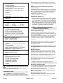 22
22
-
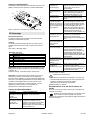 23
23
-
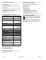 24
24
-
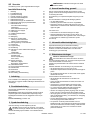 25
25
-
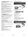 26
26
-
 27
27
-
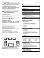 28
28
-
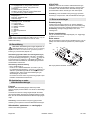 29
29
-
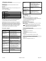 30
30
-
 31
31
-
 32
32
-
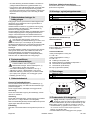 33
33
-
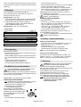 34
34
-
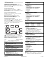 35
35
-
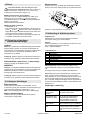 36
36
-
 37
37
-
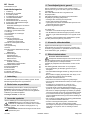 38
38
-
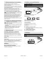 39
39
-
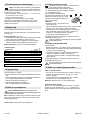 40
40
-
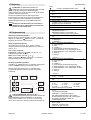 41
41
-
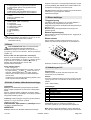 42
42
-
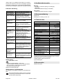 43
43
-
 44
44
-
 45
45
-
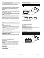 46
46
-
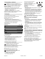 47
47
-
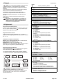 48
48
-
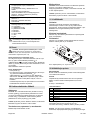 49
49
-
 50
50
-
 51
51
-
 52
52
-
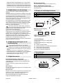 53
53
-
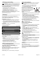 54
54
-
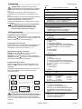 55
55
-
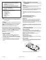 56
56
-
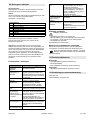 57
57
-
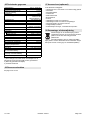 58
58
-
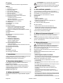 59
59
-
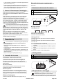 60
60
-
 61
61
-
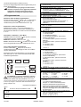 62
62
-
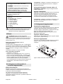 63
63
-
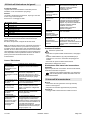 64
64
-
 65
65
-
 66
66
-
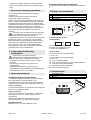 67
67
-
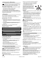 68
68
-
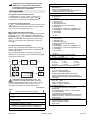 69
69
-
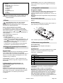 70
70
-
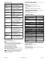 71
71
-
 72
72
-
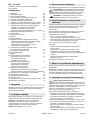 73
73
-
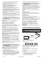 74
74
-
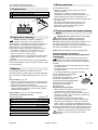 75
75
-
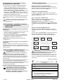 76
76
-
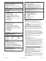 77
77
-
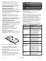 78
78
-
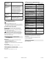 79
79
-
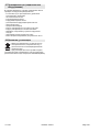 80
80
-
 81
81
-
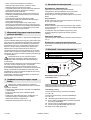 82
82
-
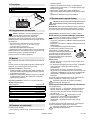 83
83
-
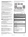 84
84
-
 85
85
-
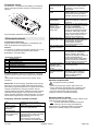 86
86
-
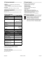 87
87
-
 88
88
-
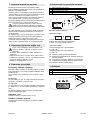 89
89
-
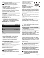 90
90
-
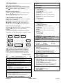 91
91
-
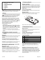 92
92
-
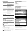 93
93
-
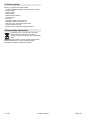 94
94
-
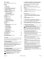 95
95
-
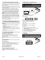 96
96
-
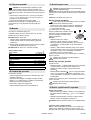 97
97
-
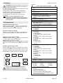 98
98
-
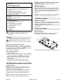 99
99
-
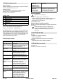 100
100
-
 101
101
-
 102
102
-
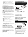 103
103
-
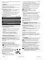 104
104
-
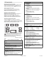 105
105
-
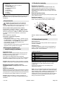 106
106
-
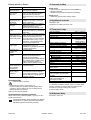 107
107
-
 108
108
-
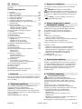 109
109
-
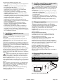 110
110
-
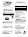 111
111
-
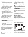 112
112
-
 113
113
-
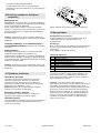 114
114
-
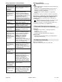 115
115
-
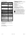 116
116
-
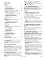 117
117
-
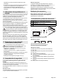 118
118
-
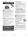 119
119
-
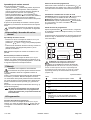 120
120
-
 121
121
-
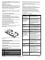 122
122
-
 123
123
-
 124
124
-
 125
125
-
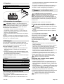 126
126
-
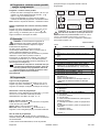 127
127
-
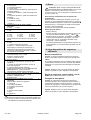 128
128
-
 129
129
-
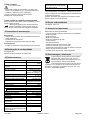 130
130
-
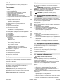 131
131
-
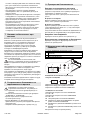 132
132
-
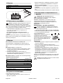 133
133
-
 134
134
-
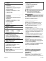 135
135
-
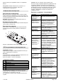 136
136
-
 137
137
-
 138
138
-
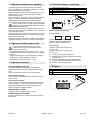 139
139
-
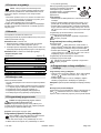 140
140
-
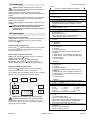 141
141
-
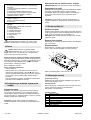 142
142
-
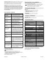 143
143
-
 144
144
-
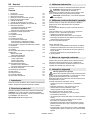 145
145
-
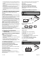 146
146
-
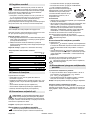 147
147
-
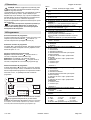 148
148
-
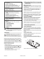 149
149
-
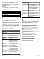 150
150
-
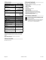 151
151
-
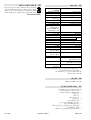 152
152
-
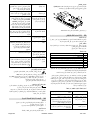 153
153
-
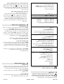 154
154
-
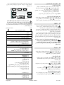 155
155
-
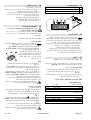 156
156
-
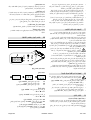 157
157
-
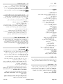 158
158
-
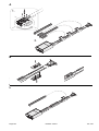 159
159
-
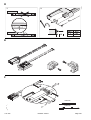 160
160
-
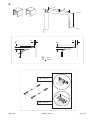 161
161
-
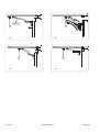 162
162
-
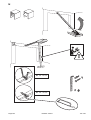 163
163
-
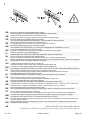 164
164
-
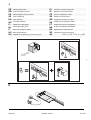 165
165
-
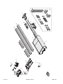 166
166
-
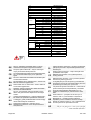 167
167
-
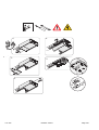 168
168
-
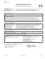 169
169
-
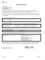 170
170
-
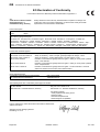 171
171
-
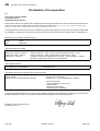 172
172
-
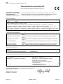 173
173
-
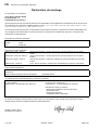 174
174
-
 175
175
-
 176
176
-
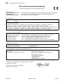 177
177
-
 178
178
-
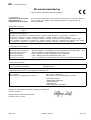 179
179
-
 180
180
-
 181
181
-
 182
182
-
 183
183
-
 184
184
-
 185
185
-
 186
186
-
 187
187
-
 188
188
-
 189
189
-
 190
190
-
 191
191
-
 192
192
-
 193
193
-
 194
194
-
 195
195
-
 196
196
-
 197
197
-
 198
198
-
 199
199
-
 200
200
-
 201
201
-
 202
202
-
 203
203
-
 204
204
-
 205
205
-
 206
206
-
 207
207
-
 208
208
-
 209
209
-
 210
210
-
 211
211
-
 212
212


V iných jazykoch
Ďalšie dokumenty
-
VITRA Dancing Wall Assembly Instructions
-
Chamberlain LiftMaster LM50K Návod na obsluhu
-
-
-
Chamberlain ML1000EV, ML700EV Návod na obsluhu
-
-
-
-
-
Biohort 10603388 Používateľská príručka