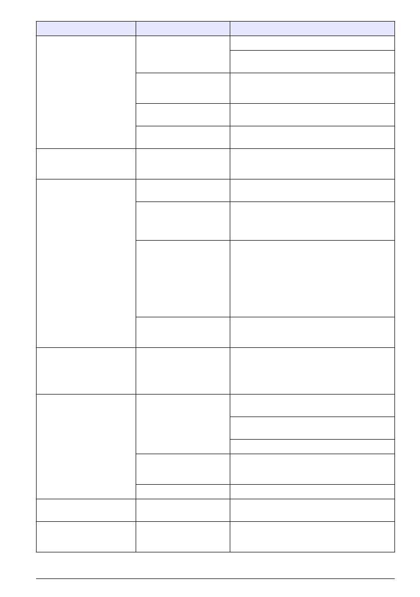
Error/Warning Description Solution
Probe Not Supported Probe disconnected or
connected improperly
Tighten the locking nut on the probe connector.
Disconnect the probe and then connect the probe
again.
Software not updated to
most current version
To download the most current version of the
software, refer to the applicable product page on
the manufacturer's website.
Problem with probe Connect a different IntelliCAL probe to the meter
to verify if problem is with the meter or the probe.
HQd meter does not
support IntelliCAL probe
Contact Technical Support.
Bootloader X.X.XX.XX error Software not updated to
most current version.
To download the most current version of the
software, refer to the applicable product page on
the manufacturer's website.
0 days remaining message
(For LDO and LBOD only)
LDO or LBOD sensor cap
used for 365 days
Replace the LDO or LBOD sensor cap and
iButton
®
.
There are 0 days remaining
in the life of the LDO sensor
cap.
Replace the LDO sensor cap. Calibration will be
allowed. However, the calibration icon and
question mark will appear on the measurement
screen even if the calibration has passed.
Meter set to incorrect date
and time
1. Disconnect the probe from the meter.
2. Remove the meter batteries.
3. Install the meter batteries properly. Follow the
polarity makings.
4. Set correct date and time in the meter.
5. Connect the probe and verify that message
has been removed.
Software not updated to
most current version
To download the most current version of the
software, refer to the applicable product page on
the manufacturer's website.
Meter not configured Software error(s) If the meter starts up correctly, back up the Data
Log and Method files.
To download the most current version of the
software, refer to the applicable product page on
the manufacturer's website.
Meter will not power on or
powers on intermittently
Batteries are not installed
correctly
Examine battery orientation to make sure the
batteries follow the polarity markings. Test again.
Clean the battery terminals, then install new
batteries.
Connect AC power adapter and test again.
Software not updated to
most current version
To download the most current version of the
software, refer to the applicable product page on
the manufacturer's website.
Damaged meter Contact Technical Support.
Unable to access Full
Access Options screen
Correct password has not
been entered
Contact Technical Support.
Unable to access Full or
Operator Access Options
screen
Software not updated to
most current version
To download the most current version of the
software, refer to the applicable product page on
the manufacturer's website.
English 17


