INSTALACIÓN
Indicaciones generales
12 | SK 2
1. Indicaciones generales
Este documento está dirigido al profesional técnico especia-
lizado.
Nota
Lea atentamente estas instrucciones antes del uso y
archívelas en un lugar seguro.
Si entrega este aparato a otros usuarios, no se olvide
de incluir las instrucciones.
1.1 Documentación relacionada
Instrucciones de utilización y de instalación de la
bomba de calor
Nota
Puede consultar la información sobre "Garantía" y
"Medio ambiente y reciclado" en las instrucciones de
utilización y de instalación del aparato.
1.2 Unidades de medida
Nota
Si no se indica lo contrario, todas las dimensiones es-
tarán expresadas en milímetros.
2. Descripción del aparato
Dimensiones
450
303
50
410
D0000069186
2.1 Ámbito de suministro
- 4 tornillos M8x30
- 4 arandelas
3. Preparativos
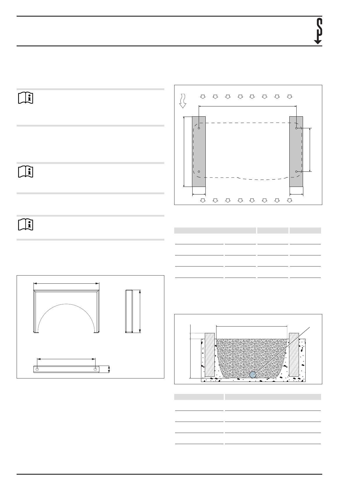
3.1 Cimiento
B
C
A
1
3
2
150150
D0000063486
1 Lado de entrada de aire
2 Lado de salida de aire
3 Dirección principal del viento
Bomba de calor A B C
3CSPlus, 3.5ACS,
07ACSclassic
850 500 408
4CSPlus, 4.5ACS,
09ACS classic
850 500 408
6CSPlus, 6.5ACS,
13ACSclassic
980 500 408
8CSPlus, 8.5ACS,
17ACSclassic
980 500 408
Coloque la cimentación lineal en el lugar de instalación de
la bomba de calor.
3.2 Lecho de grava
>800
100
a
D0000069294
1
1 Tubo de drenaje
Bomba de calor a
3CSPlus, 3.5ACS,
07ACSclassic
700
4CSPlus, 4.5ACS,
09ACS classic
700
6CSPlus, 6.5ACS,
13ACSclassic
830
8CSPlus, 8.5ACS,
17ACSclassic
830
Coloque un tubo de drenaje bajo el aparato para llevar la
humedad fuera de la casa.
INSTALACIÓN


