FR
FR-2 16601064_ed4
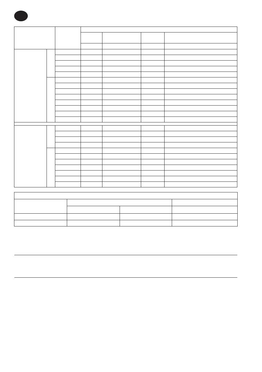
Style Modèle(s)
Informations données pour le fonctionnement des outils à 76 psi/5,3 bar
Vit.
libre
Plage de couples
d’embrayage
Couple de
calage
Couple maxi. d’exploitation recommandé
t/min
Nm Nm Nm
Angle, début en
levier
QA6
QA6AA-030 550 15-27 33 27
QA6AA-040 405 20-35 41 35
QA6AA-055 300 25-49 55 49
QA6AA-070 215 35-62 74 62
QA6AA-090 175 45-80 87 80
QA8
QA8AA-040 540 20-35 44 40
QA8AA-055 400 25-49 57 55
QA8AA-070 305 35-62 73 70
QA8AA-090 240 45-80 91 90
QA8AA-115 190 70-102 105 115
QA8AA-150 140 75-133 140 150
QA8AA-200 105 100-178 181 200
QA8AA-225 85 125-222 232 225
Droit, début en
levier
QA6
QA6AS-025 685 12-22 23 22
QA6AS-030 575 15-26 27 26
QA6AS-040 425 20-35 37 35
QA6AS-055 310 25-49 51 49
QA8
QA8AS-040 570 20-35 40 35
QA8AS-055 445 25-49 51 49
QA8AS-070 335 35-62 68 62
QA8AS-090 245 45-80 90 80
QA8AS-115 205 70-102 108 102
QA8AS-150 160 75-133 138 133
QA8AS-180 135 90-160 165 160
Toutes les informations sont données pour le fonctionnement à 90 psi/6,2 bar pour tous les modèles
Modèle
Niveau sonore dB(A) (ISO15744) Niveau de vibrations (ISO28927)
† Pression (L
p
) ‡ Puissance acoustique (L
w
) m/s
2
QA6 82.5 93.5 < 2.5
QA8 87 98 < 2.5
† K
pA
= incertitude de mesure de 3dB
‡ K
wA
= incertitude de mesure de 3dB
La plage de fonctionnement de pression d’air pour cet outil va de 76 à 90 PSI(5,3 à 6,2 bar). L’embrayage fonctionnera correctement sur cette
plage. En dehors de ces limites, il peut
connaître les symptômes décrits dans les avertissements.
Instructions de montage
Toutes les congurations avec outil droit / en ligne doivent être montées à l’aide de la bonne bride, comme indiqué dans le manuel
d’informations sur les pièces 16601072. Une bride de montage est disponible pour toutes les congurations avec outils d’angle. Consultez le
manuel d’informations sur les pièces 16601072 pour des informations de montage spéciques.
Installation et lubrication
Dimensionnez l’alimentation en air de façon à obtenir une pression maximale (PMAX) de l’outil au niveau de l’entrée d’air de l’instrument. Drain-
ez quotidiennement le condensat des vannes situées aux points bas de la tuyauterie, du ltre à air et du réservoir du compresseur. Installez un
raccordement à air de sûreté dont la taille est adaptée au tuyau et placez-le en amont de celui-ci, puis utilisez un dispositif anti-débattement sur
tous les raccords pour tuyaux sans fermeture interne, an d’empêcher les tuyaux de fouetter si l’un d’entre eux se décroche ou si le raccord se
détache. Reportez-vous au schéma 16578775 et au tableau en page 2.
La fréquence de maintenance s’ache sous la forme d’une èche circulaire et indique h pour les heures, j pour les jours et m pour les mois.
Éléments identiés comme :
1. Filtre à air 6. Taille du letage
2. Régulateur 7. Raccord
3. Lubricateur 8. Raccordement à air de sûreté
4. Vanne d’arrêt d’urgence 9. Huile
5. Diamètre du tuyau


