FRANÇAIS
16
10.1 Nettoyage du filtre d'aspiration
Déconnecter l’alimentation électrique de la
pompe.
Vidanger la pompe.
Nettoyer avec un jet d'eau et une brosse.
10.2 Nettoyage des turbines
Déconnecter l’alimentation électrique de la pompe.
Vidanger la pompe.
Desserrer les 8 vis de fixation sur la base du filtre fig.3.
Retirer la base et le filtre fig. 4.
En tenant la 1ère turbine, esserrer l'écrou fig.5.
Extraire la turbine, le diffuseur, l'anneau et le joint torique.
Le répéter pour toutes les turbines.
Rince rla pompe avec de l’eau propre pour éliminer les
éventuelles impuretés entre le moteur et la chemise de la pompe.
Nettoyer les turbines.
Vérifier que la roue peut tourner librement.
Remo nlteesr parties dans le sens inverse du démontage.
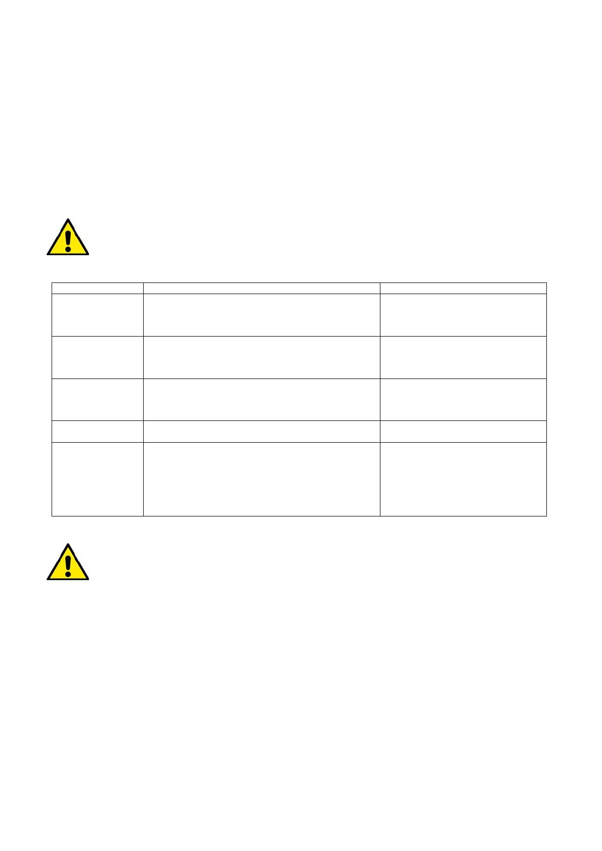
11. RECHERCHE PANNES
Avant de commencer la recherche des pannes, il faut interrompre l’alimentation électrique de la
pompe (retirer la fiche de la prise). Si le câble d’alimentation ou un composant électrique quelconque
de la pompe sont abîmés, la réparation ou le remplacement de la pièce doivent être effectués par le
Constructeur ou par son service après-vente, ou bien par une personne ayant une qualification
équivalente de manière à prévenir tout risque.
Pannes
érifications Remèdes
La pompe ne
s'allume pas
A. La pompe n'est pas alimentée.
B. Absence d'eau.
C. La pompe n’est pas activée par le flotteur.
A. Vérifier l'alimentation.
B. Contrôler le niveau de l'eau.
C. Vérifier que le flotteur bouge
librement.
La pompe ne
refoule pas
A. La crépine d’aspiration ou les tuyaux sont bouchés.
B. La roue est usée ou bloquée.
C. La hauteur demandée est supérieure aux
caractéristiques de la pompe.
A.B Éliminer les obstructions.
C. Remonter la pompe dans le puits
en fonction de ses caractéristiques
Le débit est
insuffisant.
A. Vérifier que la crépine d’aspiration n’est pas
partiellement bouchée.
B. Vérifier que la roue ou le tuyau de refoulement ne
sont pas partiellement bouchés ou incrustés.
A. Éliminer les éventuelles
obstructions.
B. Éliminer les éventuelles
obstructions.
La pompe ne
s’arrête pas.
A. La pompe n’est pas désactivée par le flotteur. A. Vérifier que le flotteur bouge
librement.
La pompe s’arrête
(intervention
possible de la
protection
thermique).
A. Vérifier que le liquide à pomper n’est pas trop dense
car il causerait la surchauffe du moteur.
B. Vérifier que la température de l’eau n’est pas trop
élevée.
C. Vérifier qu’aucun corps solides ne bloque la roue.
D. Alimentation non conforme aux données de la
plaque.
A.B.C.D. Débrancher la fiche, éliminer
la cause qui a provoqué la surchauffe,
attendre le refroidissement de la
pompe et la rebrancher.
12. GARANTIE
Toute modification non autorisée au préalable dégage le constructeur de tout type de responsabilité.
Toutes les pièces de rechange utilisées dans les réparations doivent être originales et tous les
accessoires doivent être autorisés par le constructeur de manière à pouvoir garantir le maximum de
sécurité des machines et des installations sur lesquelles ils peuvent être montés.
Ce produit est couvert par une garantie légale (dans la Communauté européenne pendant 24 mois à partir de la date
d'achat) concernant tous les défauts imputables à des vices de fabrication ou de matériau utilisé.
Le produit en garantie pourra être, à discrétion, soit remplacé par un nouveau en parfait état de fonctionnement ou
réparé gratuitement si les conditions suivantes sont observées:
le produit a été utilisé correctement et conformément aux instructions et qu'aucune tentative de réparation n'ait
été effectuée par l'acheteur ou par des tiers.
Le produit a été remis au point de vente d'achat, avec la documentation qui atteste l'achat (facture ou ticket
fiscal) et une brève description du problème rencontré.
Les turbines, les pièces sujettes à l'usure, les raccords ne sont pas concernées par la garantie. L'intervention sous
garantie n'étend en aucun cas la durée initiale.Enfin le fabricant met tout en oeuvre afin de fournir sur commande les
pièces détachées principales dites d'usure pendant une durée minimale de 5 ans après la date de fabrication figurant
dans le numéro de série.


