Dometic 7220 Návod na obsluhu
- Kategória
- Sanitárna keramika
- Typ
- Návod na obsluhu

MF7100, MF7200
Macerator Toilet
Installation Manual . . . . . . . . . . . . . . . . . . . 4
Zerhackertoilette
Montageanleitung . . . . . . . . . . . . . . . . . . 14
WC dilacérateur
Instructions de montage . . . . . . . . . . . . . 25
Inodoro triturador
Instrucciones de montaje. . . . . . . . . . . . . 36
WC con maceratore
Indicazioni di montaggio. . . . . . . . . . . . . 47
Versnijdingstoilet
Montagehandleiding . . . . . . . . . . . . . . . . 58
Findelingstoilet
Monteringsvejledning . . . . . . . . . . . . . . . 68
Maceratortoalett
Monteringsanvisning . . . . . . . . . . . . . . . . 78
Macerator-toalett
Monteringsanvisning . . . . . . . . . . . . . . . . 88
Silppuripumppu-wc
Asennusohje . . . . . . . . . . . . . . . . . . . . . . . 98
Sanita de trituração
Instruções de montagem. . . . . . . . . . . . 108
Унитаз с мацератором
Инструкция по монтажу . . . . . . . . . . . . 119
Toaleta z rozdrabniaczem
Instrukcja montażu . . . . . . . . . . . . . . . . . 129
Macerátorová toaleta
Návod na montáž . . . . . . . . . . . . . . . . . . 140
Toaleta s maceračním čerpadlem
Návod k montáži . . . . . . . . . . . . . . . . . . 140
Darálós vécé
Szerelési útmutató . . . . . . . . . . . . . . . . . 160
EN
DE
FR
ES
IT
NL
DA
SV
NO
FI
PT
RU
PL
SK
CS
HU
SANITATION
MASTERFLUSH
04_title_I_16s_Invoice.fm Seite 1 Montag, 15. August 2016 7:37 19

04_title_I_16s_Invoice.fm Seite 2 Montag, 15. August 2016 7:37 19

2
1
2
345 6 7
3
Dometic MasterFlush
A
D
E
C
A
B
1
A
B
C
D
E
G
F
3
4
B1-B2

4
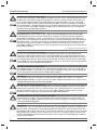
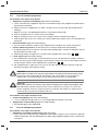
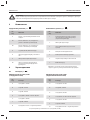
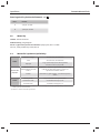
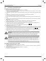
2.1 Warnings – marine applications
The following statements must be read and understood before installing, servicing and/or
operating this product on a boat. Modifi cation of this product may result in property damage.
Dometic recommends that a quali ed marine technician or electrician install or service this product.
Equipment damage, injury to personnel or death could result from improper installation. DOMETIC
ACCEPTS NO RESPONSIBILITY OR LIABILITY FOR DAMAGE TO EQUIPMENT, OR INJURY OR
DEATH TO PERSONNEL THAT MAY RESULT FROM IMPROPER INSTALLATION, SERVICE OR
OPERATION OF THIS PRODUCT.
Dometic MasterFlush Notes on using the manual
1 Notes on using the manual . . . . . . . . . . . . . . . . . . . . . . . . . . . . . . . . . . . . . . . . . . . . . . . . . 4
2 General safety instructions . . . . . . . . . . . . . . . . . . . . . . . . . . . . . . . . . . . . . . . . . . . . . . 4 – 5
3 Components . . . . . . . . . . . . . . . . . . . . . . . . . . . . . . . . . . . . . . . . . . . . . . . . . . . . . . . . . . . . 6
4 Speci cations . . . . . . . . . . . . . . . . . . . . . . . . . . . . . . . . . . . . . . . . . . . . . . . . . . . . . . . . 6 – 7
5 Installation . . . . . . . . . . . . . . . . . . . . . . . . . . . . . . . . . . . . . . . . . . . . . . . . . . . . . . . . . . 8 – 13
6 Customer service. . . . . . . . . . . . . . . . . . . . . . . . . . . . . . . . . . . . . . . . . . . . . . . . . . . . . . . .13
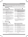
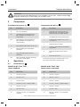
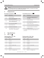
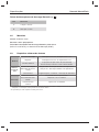
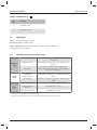
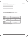
1 Notes on using the manual
Note
Supplementary information for operating the device.
fi g.
1
A, page 2 : This refers to an element in an illustration. In this example, item A in
gure 1 on page 2.
Caution!
Safety Instruction: Failure to observe this instruction can cause material damage and
impair the function of the device.
Caution! Hazard of Flooding
If the toilet is connected to ANY through-the-hull ttings, properly installed seacocks MUST
be installed in all piping connected to through-the-hull ttings. Seacocks MUST be easily
accessible to all users of the toilet or secondary valves tted in hoses where they are easily
accessible. All valves MUST be full bore valves and of marine quality. Screw-to-close gate
valves are not recommended. Failure to do so can result in ooding which can cause loss
of property and life.
EN
Table of contents
2 General safety instructions
The manufacturer will not be held liable for claims for damage resulting from the following:
• Faulty assembly or connection
• Damage to the unit from mechanical in uences, misuse or abuse
• Alterations to the unit without express written permission from the manufacturer
• Use for purposes other than those described in the operating manual
Make sure to follow any governing codes or standards that apply to your installation.

5
General safety instructions
Caution! Hazard of Flooding
If toilet uses sea water for ushing at ANY time, a sea water pump controlled by an auto-
matically operating demand switch MUST NOT be installed. If the onboard water valve or
any plumbing connections were to leak, the automatically operated pump would start and
could ood the boat. Failure to comply can cause loss of property and life.
Caution! Hazard of Flooding
Before beginning any work on this product, be sure that all electrical power to the unit has
been turned off and that seacocks are in the CLOSED or OFF position. Failure to do so can
result in ooding which can cause loss of property and life.
Caution!
Do not connect sea water ush toilet (models 7160, 7180) to an onboard potable water
system. Failure to comply could result in contamination of the potable water supply.
Caution! Hazard of Flooding
Do not connect sea water ush toilet (models 7160, 7260) to an onboard pressurized water
system. Failure to comply can result in ooding which can cause loss of property and life.
Caution! Hazard of Shock or Fire
Always use recommended fuse, circuit breaker and wire size. Failure to do so can result in
re that can cause the loss of property and life.
Caution!
Over lling the holding tank can create serious damage to the sanitation system, such
as rupturing the holding tank and releasing tank contents into the bilge. To prevent this
possibility, Dometic recommends using a “full” tank shut-down relay from the “full” signal
generated by an optional Dometic DTM01C tank monitor or DTM04 four-level tank monitor
system.
Caution! Hazard of Flooding
If toilet rim is ever less than 8 in. (20 cm) above the highest possible waterline at ANY time
(during any conditions of heel, load or trim) and is connected to ANY through-the-hull
ttings, properly positioned ventilated (vented) loops MUST be installed in intake* or dis-
charge piping to prevent potential back siphonage of sea water into the boat. Vented loops
must be equipped with integral check valve that permits air into line to prevent siphoning.
Failure to do so can result in ooding which can cause loss of property and life.
* if connected to sea water
Caution! Hazard of Flooding
If toilet is connected to ANY through-the-hull ttings, ALL exible hoses must be of marine
sanitation quality and must be secured to ANY ttings (such as those at seacock, vented
loop or toilet) with two stainless steel, worm-drive hose band clamps at each connection.
Connections MUST be checked frequently for integrity. Failure to comply can result in
ooding which can cause loss of property and life
.
Dometic MasterFlush

6
Components
Caution!
Discharge of sewage directly overboard is illegal in some areas. Please check all local laws
before operating an overboard discharge sanitation system.
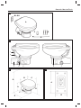
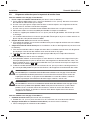
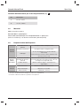
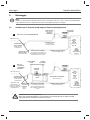
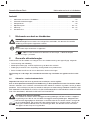
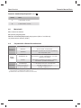
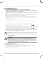
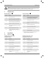
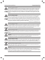
3 Components
Carton contents ( g.
1
)
Toilet components ( g.
2
)
Ref. Description
A Macerator toilet
B1 DFS-2F ush switch (standard -
freshwater ush toilet)
B2 DFS-1F ush switch (standard -
sea water ush toilet)
C 1.5 in. (38 mm) discharge tting
D Floor mounting hardware kit
E Water supply hose kit
NS Parts list, installation and operation
instructions, quick-start guide
Ref. Description
1 Rim ush check valve (freshwater
toilet) or adapter (sea water model)
2 Water supply hose
3 Macerator pump
(under plastic cover)
4 Electric water valve
5 Product ID label location
6 Stainless steel compression band
7 Discharge tting
Refer to complete parts list (packed separately)
for additional information.
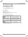
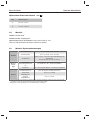
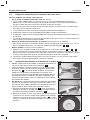
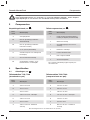
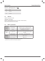
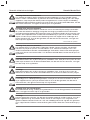
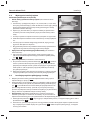
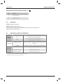
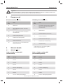
4 Specifi cations
4.1 Dimensions ( g.
3
)
Ref. Dimension
A 13.25 in. / 337 mm
B 14.5 in. / 368 mm
C 18.75 in. / 476 mm
D 12.25 in. / 311 mm - seat height
E 13.75 in. / 349 mm
F 10 in. / 254 mm
G 26.25 in. / 667 mm - seat lid up
Ref. Dimension
A 14.75 in. / 375 mm
B 15 in. / 381 mm
C 19 in. / 483 mm
D 13.75 in. / 349 mm - seat height
E 13.75 in. / 349 mm
F 10 in. / 254 mm
G 28.75 in. / 730 mm - seat lid up
Toilet models 7220, 7260
(compact marine bowl)
Toilet models 7120, 7160
(standard bowl)
All dimensions may vary 0.375 in. (10 mm)
Dometic MasterFlush

7
Specifications
Dometic fl ush switch panel
( g.
4
)
Ref. Dimension
A 3.25 in. / 83 mm
B 1.625 in. / 41 mm
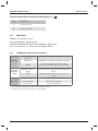
4.3 Minimum System Requirements
4.2 Materials
Toilet: vitreous ceramic
Toilet base: polypropylene
Dometic fl ush switch panel: polystyrene (DFS-1F or DFS-2F);
or powder-coated aluminum (DFST)
Electrical
Power draw 20 amps/12 V DC; 10 amps/24 V DC
Circuit breaker 25 amps/12 V DC; 15 amps/24 V DC
Wiring
12 ga. (up to 25 ft./7.6 m total circuit)
Consult ABYC guidelines for additional information.
Water
Supply
Fitting size
Supply hose ID
0.5 in. NPT – fresh water ush toilet
0.75 in./19 mm ID – sea water ush toilet
Flow rate 2.0 gpm/7.6 lpm minimum – fresh water ush
Discharge
Inside diameter 1.5 in./38 mm or 1 in./25 mm
Horizontal run* 40 ft./12.2 m maximum
Vertical run* 4 ft./1.2 m maximum
* Horizontal and vertical run distances are not cumulative. Check for adequate discharge ow
if installation nears one of these limits.
Speci cations are subject to change without notice.
Dometic MasterFlush

8
0.75 in./
19 mm
SEACOCK
1 in./ 25 mm
or 1.5 in./38 mm
SEACOCK
0.75 in./
19 mm
SEACOCK
1 in./ 25 mm
or 1.5 in./38 mm
SEACOCK
MAKE LOOP
12 in./305 mm
ABOVE FLOOR
MACERATOR
TOILET
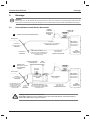
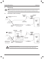
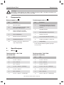
Installation
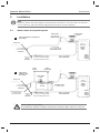
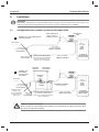
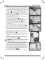
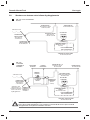
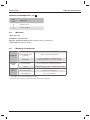
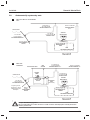
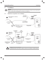
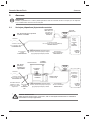
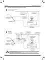
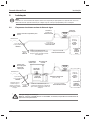
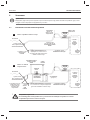
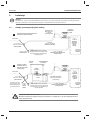
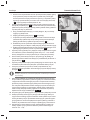
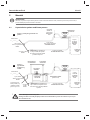
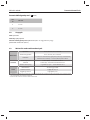
5 Installation
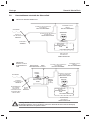
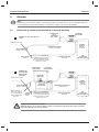
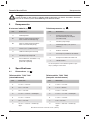
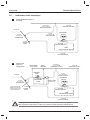
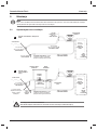
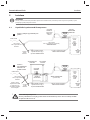
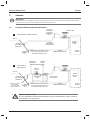
5.1 Above water line system layouts
Note
Determine whether the water supply to the toilet will be fresh water or sea water, above or below the
vessel’s water line, and then follow the appropriate instructions for the installation.
5
6
VENT
FITTING
0.75 in./ 19 mm ID
SEA WATER LINE
0.75 in./ 19 mm ID
SEA WATER LINE
0.5 in./
13 mm ID
FRESH
WATER
LINE
0.5 in./
13 mm ID
FRESH
WATER
LINE
FROM
FRESH
WATER
SUPPLY
FROM
FRESH
WATER
SUPPLY
CHECK VALVE is needed
to ensure sea water pump
stays primed between uses
CHECK VALVE is needed
to ensure sea water pump
stays primed between uses
Add vented loop here
if holding tank is
below water line.*
1 in./ 25 mm
or 1.5 in./38 mm ID
SANITATION HOSE
VENT
FILTER
HOLDING TANK
(cut-away view)
DISCHARGE
PUMP
DECK
DISCHARGE
WATER LINE
WATER LINE
Toilet with direct overboard
discharge
Toilet with
holding tank
discharge
Caution! Hazard of Flooding
All vented loops should be installed a minimum of 8 in./20 cm above water line at full heel.
*
Dometic MasterFlush

9
HOLDING
TANK
(cut-away
view)
1 in./25 mm or
1.5 in./38 mm ID
SANITATION HOSE
0.75 in./
19 mm
SEACOCK
1 in./ 25 mm
or 1.5 in./38 mm
SEACOCK
FROM
FRESH WATER SUPPLY
FROM
FRESH WATER SUPPLY
0.75 in./
19 mm
SEACOCK
1 in./ 25 mm
or 1.5 in./38 mm
SEACOCK
MACERATOR
TOILET
MACERATOR
TOILET
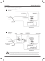
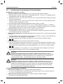
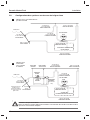
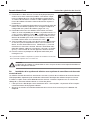
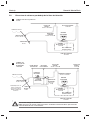
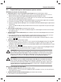
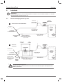
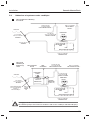
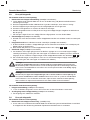
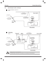
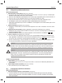
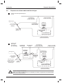
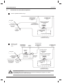
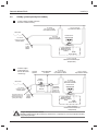
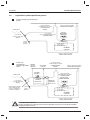
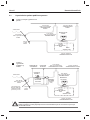
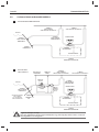
Installation
5.2 Below water line system layouts
7
8
VENT
FITTING
0.75 in./ 19 mm ID
SEA WATER LINE
0.75 in./ 19 mm ID
SEA WATER LINE
0.75 in./ 19 mm ID
VENTED LOOP *
0.75 in./ 19 mm ID
VENTED LOOP *
0.5 in./ 13 mm ID
FRESH WATER LINE
0.5 in./ 13 mm ID
FRESH WATER LINE
Add vented loop here
if holding tank is
below water line.*
1 in./25 mm or
1.5 in./38 mm ID
VENTED LOOP *
1 in./25 mm or
1.5 in./38 mm ID
VENTED LOOP *
VENT
FILTER
DISCHARGE
PUMP
DECK
DISCHARGE
Toilet with direct overboard
discharge
Toilet with
holding tank
discharge
Caution! Hazard of Flooding
All vented loops should be installed a minimum of 8 in./20 cm above water line at full heel.
*
1 in./ 25 mm
or 1.5 in./38 mm ID
SANITATION HOSE
WATER LINE
WATER LINE
Dometic MasterFlush

10
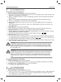
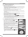
5.3 Inlet plumbing requirements
For sea water fl ush models:
1. Seacock and inlet water line (not supplied with toilet):
a. 3/4 in. (19 mm) full- ow seacock and 3/4 in. (19 mm) ID exible hose. Follow seacock
manufacturer’s installation instructions.
b. Make sure inlet seacock is below sea water line at all times, during all conditions of full heel.
c. Make sure all inlet hose connections have no sharp bends or restrictions.
d. Use two stainless steel hose clamps at each connection.
e. Provide hose support every 3 ft. (0.9 m) along inlet hose run to limit movement.
f. Keep hose runs as short as possible. Eliminate sags or low spots that may hinder ow.
2. Water inlet strainer (not supplied with toilet)
a. 100-mesh strainer is recommended between inlet seacock and sea water ush toilet.
3. Inlet check valve for above-waterline installations (not supplied with toilet):
a. A check valve should be installed in inlet supply line to assure toilet’s sea water pump stays
primed between ushes.
b. Check valve should be located as close as possible to the inlet seacock (
5
,
6
).
4. Vented loop (not supplied with toilet):
a. If the toilet rim will ever be less than 8 in. (20 cm) above the highest possible waterline at any
point of heel, trim or load, then a 3/4 in. (19 mm) vented loop must be installed in the inlet
hose between the inlet seacock and the toilet (
7
,
8
).
b. Vented loop must be positioned a minimum of 8 in. (20 cm) above highest possible waterline
during all conditions of heel, trim or load.
Warning!
Do not connect sea water fl ush toilet inlet line to a pressurized freshwater system.
This will result in a continuously running freshwater pump, which can possibly over ow
the toilet bowl, ood the boat, and cause potential loss of property or life.
Warning!
Do not connect sea water fl ush toilet inlet line to an onboard potable water system
in any way. This can cause contamination of the potable water system. If fresh water
is desired, purchase the freshwater- ush version of the toilet, or provide a separate
freshwater tank that supplies water only to the toilet.
For freshwater fl ush models:
1. Inlet water line (not supplied with toilet):
a. 0.5 in. (13 mm) ID exible hose with 1/2 in. NPT tting connects to toilet water valve.
2. Shut-off valve in inlet line (not supplied with toilet):
a. For toilet cleaning and maintenance.
Installation
Dometic MasterFlush

11
Installation
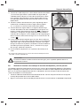
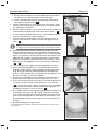
5.4 Outlet plumbing requirements
For sea water fl ush models:
1. Seacock and outlet sanitation hose (not supplied):
a. 1 in. (25 mm) or 1.5 in. (38 mm) full- ow seacock and exible
hose to route waste to a holding tank with discharge pump,
or route directly overboard. Follow seacock manufacturer’s
instructions.
b. Make sure waste outlet seacock is both aft and higher than
the water inlet seacock.
c Outlet plumbing should have no sharp bends or restrictions.
d. Use two stainless steel hose clamps at each connection.
e. Provide support along entire hose run to limit movement and
side-loading on connections.
f. Keep hose runs as short as possible. Eliminate sags or low
spots that may hinder ow.
2. Discharge hose loop near toilet (not supplied with toilet):
a. To retain water in toilet bowl, make a 12 in. (30 cm) high loop
in discharge line as near to toilet as possible
( gs.
5
,
6
).
3. Vented loop (not supplied with toilet):
a. Refer to toilet system layout gures
6
and
7
–
8
for
recommended locations of discharge vented loops connect-
ed to system components that are below the water line or
may be less than 8 in. (20 cm) above highest possible water
line at full heel.
b. Vented loops must be positioned a minimum of 8 in. (20 cm)
above highest possible water line at full heel.
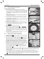
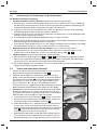
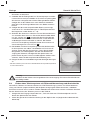
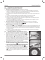
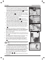
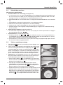
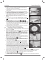
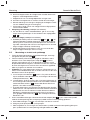
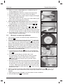
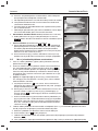
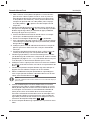
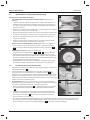
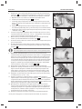
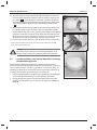
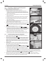
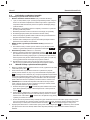
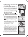
5.5 Toilet and fl ush switch installation
1. Carefully unpack toilet, water supply hose, discharge tting
and hardware ( g.
1
).
2. Place toilet in desired location on oor. If necessary, rotate
toilet so that macerator pump housing ( g.
2
3) does not
interfere with walls, or so that it will better accommodate the
intended plumbing layout. Con rm adequate clearance is
available for plumbing connections, and also the seat and lid
in raised position. Mark oor where toilet will be installed.
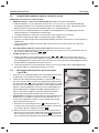
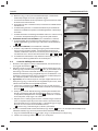
3. (Optional) If macerator pump and base must be positioned at
an angle so that toilet bowl does not face in correct direction,
the upper bowl can be rotated to the proper position:
a. Loosen compression band (
9
) just enough to slip down
past lower plastic clamp, and remove upper and lower
plastic clamps (
10
).
b. Lift bowl. Make sure notch in black rubber gasket sits around shallow pin on toilet base and
remains centered between bowl and base (
11
). Rotate bowl to desired position, then set it
down on gasket.
c. Re-position plastic clamps and compression band between upper bowl and base. Join
clamps together at front of toilet bowl (there will be a space between the clamps behind the
bowl). With compression band screw positioned on a clamp (not in gap between clamps)
(
9
), tighten compression band to 65 in.-lbs.
9
12
13
10
11
Dometic MasterFlush

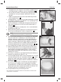
12
Installation
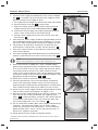
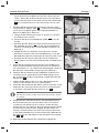
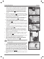
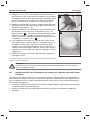
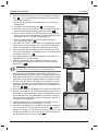
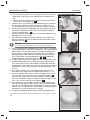
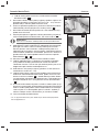
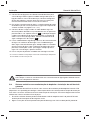
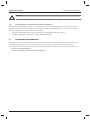
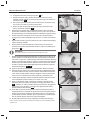
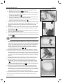
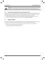
4. Connect water supply hose between check valve or adapter
( g.
2
1) and water valve (freshwater ush model) or water
pump (sea water ush model) on base.
a. Cut supply hose to length that will not kink when connected.
b. Remove plastic cover ( g.
2
3) from pump.
c. With hose clamp, attach hose to water valve (freshwater
model) or pump (sea water model) barbed tting (
12
).
d. Place loose end of supply hose up through hole of plastic
cover. Lower and t cover to macerator pump.
e. Connect water supply hose to rim ush check valve with
hose clamp (
13
).
5. Plan electrical, water supply and discharge plumbing accord-
ing to appropriate toilet system layout (see pages 8 – 9). Cre-
ate access holes for plumbing and electrical supplies to toilet.
6. Place toilet in nal location, and fasten it to oor with hex
head fasteners and washers at sides and rear of base (
14
).
7. Plan ush switch location so that electrical connections and
wires cannot get wet.
8. Use switch template (packed separately) to mark location of
fasteners and switch access hole. Cut out access hole (
15
).
Note
Refer to wiring diagram on reverse side of toilet parts list.
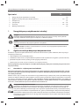
9. WITH ELECTRICAL POWER OFF, route stranded copper
positive wire (gauge per ABYC standards) from circuit break-
er or fuse to switch access hole.* Route red wire from toilet’s
macerator pump to switch access hole. Route wire from
switch access hole to electric water valve at bottom of toilet
(freshwater model). Connect wires according to diagram with
appropriate spade connectors (
15
,
17
).
10. Attach ush switch to wall with screws provided.
11. Connect ground wires from macerator pump and electric
water valve (freshwater models only) to vessel’s electrical
ground wiring according to the wiring diagram. Provide extra
wire at toilet to easily remove from oor in case of service.
12. Route vessel’s water supply and discharge plumbing to toilet
(refer to toilet system layout gures on pages 8 – 9).
13. Securely connect all discharge hoses with two stainless steel
hose clamps with screws positioned 180° opposite each
other (
16
). Lubricate ttings and hoses with silicone grease
to make hose connection easier. For freshwater toilet, con-
nect water supply with 0.5 in. NPT tting (
17
).
14. For sea water ush model, open water supply and discharge
seacocks. For freshwater model, turn on water supply.
Check for water leaks at all connections. Turn on electrical
power to toilet, press “Flush” switch and check for leaks. If
leak occurs, tighten connection.
15. Attach plastic covers to oor mounting fasteners.
* If toilet system includes any DTM series tank monitor system, refer to
Section 5.6.
14
17
15
16
18
Dometic MasterFlush

13
There is a strong, worldwide network to assist
in servicing and maintaining your sanitation
system. For the Authorized Service Center near
you, please call from 8:00 a.m. to 5:00 p.m.
(ET) Monday through Friday.
You may also contact or have your local
dealer contact the Parts Distributor nearest
you for quick response to your replacement
parts needs. They carry a complete inventory
for the Dometic sanitation product line.
Telephone: 1 800-321-9886 U.S.A. and Canada
330-439-5550 International
Fax: 330-496-3097 U.S.A. and Canada
330-439-5567 International
Web site: http://www.Dometic.com
6 Customer service
Installation
5.6 Toilet system with tank monitor and shut-down relay installation
Dometic MasterFlush toilets operate with Dometic DTM tank monitor systems (available separately)
to shut down electrical power to the toilet when the holding tank is full. This prevents over lling the
holding tank. Refer to toilet system wiring diagram on parts list.
1. Route input power wire from “full tank” relay of DTM panel to toilet’s ush switch location.
2. Follow ush switch installation instructions beginning at Section 5.5, step 10.
DOMETIC CORPORATION
SANITATION DIVISION
13128 SR 226 | PO BOX 38
BIG PRAIRIE, OHIO 44611 USA
www.Dometic.com
© 2014 Dometic Corporation
All rights reserved
600347006 11/13
Caution
Do not operate toilet without water supply turned on. Damage to internal components
may occur.
Dometic MasterFlush

14
2.1 Warnungen – Einsatz auf Booten
Vor Installation, Wartung und Einsatz auf einem Boot müssen die folgenden Anweisungen gelesen
und verstanden werden. Werden Änderungen an diesem Produkt vorgenommen, kann dies zu Sach-
schäden führen.
Dometic emp ehlt, die Installation und Wartung dieses Produkts von einem quali zierten Schiffstechniker
oder Elektriker vornehmen zu lassen. Eine unsachgemäße Installation kann zu Sachschäden, Verletzungen
oder zum Tod führen. DOMETIC ÜBERNIMMT KEINERLEI VERANTWORTUNG ODER HAFTUNG FÜR
SACHSCHÄDEN SOWIE VERLETZUNGEN ODER DEN TOD VON PERSONEN INFOLGE EINER UNSACH-
GEMÄSSEN INSTALLATION, WARTUNG ODER NUTZUNG DIESES PRODUKTS.
Dometic MasterFlush Hinweise zur Benutzung der Anleitung
1 Hinweise zum Verwenden der Anleitung . . . . . . . . . . . . . . . . . . . . . . . . . . . . . . . . . . . . . . 14
2 Allgemeine Sicherheitshinweise . . . . . . . . . . . . . . . . . . . . . . . . . . . . . . . . . . . . . . . . 14 – 16
3 Systembauteile . . . . . . . . . . . . . . . . . . . . . . . . . . . . . . . . . . . . . . . . . . . . . . . . . . . . . . . . .16
4 Spezi kationen . . . . . . . . . . . . . . . . . . . . . . . . . . . . . . . . . . . . . . . . . . . . . . . . . . . . . 16 – 17
5 Montage . . . . . . . . . . . . . . . . . . . . . . . . . . . . . . . . . . . . . . . . . . . . . . . . . . . . . . . . . . 18 – 22
6 Kundendienst . . . . . . . . . . . . . . . . . . . . . . . . . . . . . . . . . . . . . . . . . . . . . . . . . . . . . . . . . . 23
1 Hinweise zum Verwenden der Anleitung
Hinweis
Ergänzende Informationen zur Bedienung des Gerätes.
Abb.
1
A, Seite 2 : Bezeichnet ein Element in einer Abbildung. In diesem Beispiel
Element A in Abbildung 1 auf Seite 2.
Achtung!
Sicherheitshinweis: Nichtbeachtung kann zu Materialschäden führen und die Funktion des
Gerätes beeinträchtigen.
Achtung! Gefahr von Wassereinbrüchen
Wenn die Toilette über IRGENDWELCHE Borddurchlässe angeschlossen ist, müssen in alle
Rohrleitungen, die mit Borddurchlässen verbunden sind, Seeventile eingebaut werden. Die
Seeventile MÜSSEN für alle Benutzer der Toilette leicht zugänglich sein, oder es müssen leicht
zugängliche Zweitventile mit entsprechenden Verbindungsschläuchen installiert werden. Bei
allen Ventilen muss es sich um seewasserfeste Ventile mit voller Bohrung handeln. Schieberven-
tile mit Schraubverschluss werden nicht empfohlen. Andernfalls kann es zu Wassereinbrüchen
kommen, wobei die Gefahr von Unfällen mit Todesfolge oder Sachschäden besteht.
DE
Inhalt
2 Allgemeine Sicherheitshinweise
Der Hersteller übernimmt keine Haftung für Schäden aufgrund von:
• Montage- oder Anschlussfehlern
• Schäden am Gerät durch mechanische Einwirkung sowie unsachgemäße oder falsche Benutzung
• Modi kationen am Gerät ohne ausdrückliche Genehmigung des Herstellers
• Verwendung für andere als die in der Anleitung beschriebenen Zwecke.
Vergewissern Sie sich, dass Sie bei der Montage alle geltenden Vorschriften und Normen befolgen.

15
Grundlegende Sicherheitshinweise
Achtung! Gefahr von Wassereinbrüchen
Wenn JEMALS Seewasser zum Spülen der Toilette verwendet wird, DARF KEINE Seewas-
serpumpe installiert werden, die durch einen automatischen, bei Bedarf aktivierten Schalter
gesteuert wird. Im Fall eines Lecks des an Bord be ndlichen Wasserventils oder einer Leitungs-
verbindung würde die automatisch gesteuerte Pumpe starten und könnte das Boot über uten.
Andernfalls besteht die Gefahr von Unfällen mit Todesfolge oder Sachschäden.
Achtung! Gefahr von Wassereinbrüchen
Stellen Sie vor den Arbeiten an diesem Produkt sicher, dass die Stromversorgung der Toilette
abgeschaltet ist und die Seeventile in der Stellung GESCHLOSSEN bzw. AUS stehen. Andern-
falls kann es zu Wassereinbrüchen kommen, wobei die Gefahr von Unfällen mit Todesfolge oder
Sachschäden besteht.
Achtung!
Schließen Sie keine Toiletten mit Seewasserspülung (Modelle 7160, 7180) an Trinkwassersyste-
me an. Andernfalls kann der Trinkwasservorrat kontaminiert werden.
Achtung! Gefahr von Wassereinbrüchen
Schließen Sie keine Toiletten mit Seewasserspülung (Modelle 7160, 7260) an Wassersysteme
mit Außenborddruck an. Andernfalls kann es zu Wassereinbrüchen kommen, wobei die Gefahr
von Unfällen mit Todesfolge oder Sachschäden besteht.
Achtung! Kurzschluss- und Brandgefahr
Verwenden Sie immer eine Sicherung, einen Schutzschalter und Leitungen der vorgeschriebe-
nen Größe. Andernfalls besteht die Gefahr von Unfällen mit Todesfolge oder Sachschäden.
Achtung!
Das Überfüllen des Schmutzwassertanks kann gravierende Schäden an der Sanitäranlage nach
sich ziehen, wie z.B. einen Bruch des Tanks, wodurch dessen Inhalt in die Bilge ießen könnte.
Um diese Möglichkeit auszuschließen, emp ehlt Dometic die Verwendung eines Absperrrelais
für den Zustand „Tank voll“, dessen Signal von einer Tanküberwachung DTM01C von Dometic
oder einer vierstu gen Tanküberwachung DTM04 erzeugt wird.
Achtung! Gefahr von Wassereinbrüchen
Wenn sich der Rand der Toilette JEMALS weniger als 20cm (8in) oberhalb der höchstmögli-
chen Wasserlinie be ndet (bei Krängung, Beladung oder Trimmen) und über IRGENDWELCHE
Borddurchlässe angeschlossen ist, MÜSSEN in die Einlass*- oder Auslassleitung ordnungsge-
mäß angebrachte Entlüftungsbögen installiert werden, um einen Rück uss des Seewassers in
das Boot zu verhindern. Entlüftungsbögen müssen mit integrierten Rücklaufventilen versehen
werden, welches Luft in die Leitung lässt, um den Wasserrück uss zu verhindern. Andernfalls
kann es zu Wassereinbrüchen kommen, wobei die Gefahr von Unfällen mit Todesfolge oder
Sachschäden besteht.
* Wenn eine Verbindung zum Seewasser besteht.
Achtung! Gefahr von Wassereinbrüchen
Wenn die Toilette über IRGENDWELCHE Borddurchlässe angeschlossen ist, müssen ALLE
Schläuche seefest und für Sanitäranlagen geeignet und an ALLEN Anschlüssen (z.B. am See-
ventil, am Entlüftungsbogen und an der Toilette) mit zwei Edelstahlschellen mit Schneckenge-
winde befestigt sein. Die Verbindungen MÜSSEN regelmäßig auf ihre Unversehrtheit überprüft
werden. Andernfalls kann es zu Wassereinbrüchen kommen, wobei die Gefahr von Unfällen mit
Todesfolge oder Sachschäden besteht
.
Dometic MasterFlush

16
Komponenten
Achtung!
Die direkte Verklappung von Abwässern ist in manchen Jurisdiktionen untersagt. Bitte
vergewissern Sie sich beim Betrieb einer Sanitäranlage mit Bordauslass, dass Sie alle örtlich
geltenden Gesetze einhalten.
3 Systembauteile
Inhalte des Kartons (Abb.
1
)
Bauteile der Toilette (Abb.
2
, Seite2)
Ref. Beschreibung
A Zerhackertoilette
B1 Spülschalter DFS-2F (Standard–
Toiletten mit Frischwasserspülung)
B2 Spülschalter DFS-2F (Standard–
Toiletten mit Seewasserspülung)
C Entlüftungsverschraubung,
38mm/1,5in
D Montagesatz für die Fußbodenbe-
festigung
E Wasserzuleitungsschlauch, Satz
NS Teileliste, Montage und Betriebsanlei-
tung, Schnellstartanleitung
Ref. Beschreibung
1 Rückschlagventil Randspülung
(Toilette mit Frischwasserspülung)
oder Adapter (Seewasser-Modell)
2 Wasserzuleitungsschlauch
3 Zerhackerpumpe
(unter Kunststoffab-
deckung)
4 Elektrisches Wasserventil
5 Anbringungsort für Aufkleber mit
Produkt-ID
6 Quetschverschraubung aus rostfreiem
Stahl
7 Ab ussanschluss
Weitere Informationen nden Sie in der vollständi-
gen Stückliste (separat verpackt).
4 Spezifi kationen
4.1 Abmessungen (Abb.
3
)
Ref. Abmessungen
A 337 mm / 13,25 in
B 368 mm / 14,5 in
C 476 mm / 18,75 in
D 311 mm / 12,25 in – Sitzhöhe
E 349 mm / 13,75 in
F 254 mm / 10 in
G 667 mm / 26.25 in –
bei geöffnetem Deckel
Ref. Abmessungen
A 375 mm / 14,75 in
B 381 mm / 15 in
C 483 mm / 19 in
D 349 mm / 13,75 in – Sitzhöhe
E 349 mm / 13,75 in
F 254 mm / 10 in
G 730 mm / 28.75 in –
bei geöffnetem Deckel
Toilettenmodelle 7220, 7260
(Kompakt-Schüssel für den Bootseinbau)
Toilettenmodelle 7120, 7160
(Standard-Schüssel)
Alle Abmessungen können variieren (um +/-10mm / 0,375in).
Dometic MasterFlush

17
Spezi kationen
Spülschalter-Panel von Dometic
(Abb.
4
)
Ref. Abmessungen
A 83 mm / 3,25 in
B 41 mm / 1,625 in
4.3 Mindest-Systemanforderungen
4.2 Material
Toilette: Glaskeramik
Toilettensockel: Polypropylen
Spülschalter-Panel von Dometic: Polystyren (DFS-1F und
DFS-2F) oder pulverbeschichtetes Aluminium (DFST)
Elektrik
Stromaufnahme 20A/12V GS; 10A/24V GS
Schutzschalter 25 A / 12 V GS; 15 A / 24 V GS
Verdrahtung
AWG 12 (max. 7,6m/25ft Gesamtkabellänge im
Stromkreis)
Siehe ABYC-Richtlinien für weitere Informationen.
Wasser-
versor-
gung
Passender
Versorgungsschlauch,
ID
0,5in NPT – Frischwasserspülung
19mm/0,75in ID – Seewasserspülung
Durch uss min. 7,6l/min/2,0gal/min – Frischwasserspülung
Abfl uss
Innendurchmesser min. 38mm/1,5in oder 25mm/1in
Horizontale
Förderdistanz*
max. 12,2 m/40 ft
Vertikale
Förderdistanz*
max. 1,2m/4ft
* Die horizontalen und vertikalen Förderdistanzen sind nicht kumulativ. Stellen Sie einen ausreichenden
Durch uss sicher, falls sich Ihre Montage diesen Grenzwerten nähert.
Änderungen an den Spezi kationen ohne Ankündigung vorbehalten.
Dometic MasterFlush

18
19mm/
0,75in
SEEVENTIL
25mm/1in
oder 38 mm/1,5 in
SEEVENTIL
19mm/0,75in
SEEVENTIL
25mm/1in
oder 38 mm/1,5 in
SEEVENTIL
BOGEN
EINBAUEN,
305mm/12in
ÜBER DECK-
HÖHE
ZERHACKER-
TOILETTE
Montage
5 Montage
5.1 Konstruktionen oberhalb der Wasserlinie
Hinweis
Entscheiden Sie, ob die Toilette mit einer Frischwasser- oder einer Seewasser-Versorgung über oder unter der
Wasserlinie ausgestattet werden soll. Befolgen Sie anschließend die entsprechenden Montageanweisungen.
5
6
ENTLÜFTUNGSVER-
SCHRAUBUNG
0,75 in/19 mm)
Innendurchm.
SEEWASSERLEITUNG
0,75 in/19 mm)
Innendurchm.
SEEWASSERLEITUNG
FRISCHWAS-
SERLEITUNG
0,5in/13mm)
Innendurchm.
FRISCHWAS-
SERLEITUNG
0,5in/13mm)
Innendurchm.
VOM
FRISCHWAS-
SERZULAUF
VOM
FRISCHWAS-
SERZULAUF
RÜCKSCHLAGVENTIL – zur
Sicherstellung der Vorfüllung der
Seewasserpumpe während der
Betriebspausen
RÜCKSCHLAGVENTIL – zur
Sicherstellung der Vorfüllung der
Seewasserpumpe während der
Betriebspausen
Hier Entlüftungsbogen
einbauen, falls sich der
Schmutzwassertank
unterhalb der Wasser-
linie befi ndet.
25mm/1in
oder 38mm/1,5in Innendurchm.
ABWASSERSCHLAUCH
ENTLÜFTUNGS-
FILTER
ABWASSERTANK
(im Schnitt)
AUSLAS-
SPUMPE
DECK-
AUSLASS
WASSERLINIE
WASSERLINIE
Toilette mit direktem Bordauslass
Toilette mit
Auslass in einen
Schmutzwas-
sertank
Achtung! Gefahr von Wassereinbrüchen
Alle Entlüftungsbogen müssen mindestens 20cm/8in oberhalb der bei maximaler Krängung
auftretenden Wasserlinie eingebaut werden.
*
Dometic MasterFlush

19
ABWAS-
SERTANK
(im
Schnitt)
25mm/1in oder 38mm/
1,5in Innendurchm.
ABWASSERSCHLAUCH
19mm/
0,75in
SEEVENTIL
25mm/1in
oder 38 mm/1,5 in
SEEVENTIL
VOM
FRISCHWASSERZULAUF
VOM
FRISCHWASSERZULAUF
19mm/0,75in
SEEVENTIL
25mm/1in
oder 38 mm/1,5 in
SEEVENTIL
ZERHACKER-
TOILETTE
ZERHACKER-
TOILETTE
Montage
5.2 Konstruktionen unterhalb der Wasserlinie
7
8
ENTLÜFTUNGS-
VERSCHRAUBUNG
0,75 in/19 mm)
Innendurchm.
SEEWASSERLEITUNG
0,75 in/19 mm)
Innendurchm.
SEEWASSERLEITUNG
19mm/0,75in Innen-
durchm.
ENTLÜFTUNGSBOGEN *
19mm/0,75in Innen-
durchm.
ENTLÜFTUNGSBOGEN *
0,5in/13mm)
Innendurchm.
FRISCHWASSERLEI-
TUNG
0,5in/13mm Innen-
durchm.
FRISCHWASSERLEI-
TUNG
Hier Entlüftungsbo-
gen einbauen,
falls sich der
Schmutzwassertank
unterhalb der Was-
serlinie befi ndet.
25mm/1in oder 38mm/1,5in
Innendurchm.
ENTLÜFTUNGSBOGEN *
25mm/1in oder 38mm/1,5in
Innendurchm.
ENTLÜFTUNGSBOGEN *
ENTLÜFTUNGS-
FILTER
AUSLAS-
SPUMPE
DECK-
AUSLASS
Toilette mit direktem Bordauslass
Toilette mit
Auslass in einen
Schmutzwasser-
tank
Achtung! Gefahr von Wassereinbrüchen
Alle Entlüftungsbogen müssen mindestens 20cm/8in oberhalb der bei maximaler Krängung
auftretenden Wasserlinie eingebaut werden.
*
25mm/1in oder 38mm/1,5in
Innendurchm.
ABWASSERSCHLAUCH
WASSERLINIE
WASSERLINIE
Dometic MasterFlush

20
5.3 Anforderungen für die Montage der Einlassleitungen
Für Modelle mit Seewasserspülung
1. Seeventil und Einlass-Wasserleitung (nicht im Lieferumfang der Toilette enthalten):
a. Seeventil (ganz zu öffnen), 19mm/0,75in und exibler Schlauch, 19mm/0,75in. Befolgen Sie die
Montageanleitung des Herstellers des Seeventils.
b. Vergewissern Sie sich, dass das Einlass-Seeventil sich zu jeder Zeit (bei voller Krängung) unterhalb
der Wasserlinie be ndet.
c. Vergewissern Sie sich, dass alle Anschlüsse der Einlassschläuche keine scharfen Biegungen oder
Durch uss-Beeinträchtigungen aufweist.
d. Verwenden Sie bei jeder Verbindung doppelte Schlauchschellen aus Stahl.
e. Stützen Sie den Einlassschlauch alle 0,9m/3ft ab, um übermäßige Bewegungen zu verhindern.
f. Halten Sie die Länge der Schläuche so kurz wie möglich. Vermeiden Sie Durchhängen und niedrig
hängende Abschnitte, die sich negativ auf den Durch uss auswirken können.
2. Filtersieb für Wassereinlass (nicht im Lieferumfang der Toilette enthalten)
a. Es wird empfohlen, zwischen Einlass-Seeventil und Toilette mit Meerwasserspülung ein Filtersieb
mit einer Mesh-Größe von 100 einzubauen.
3. Einlass-Rückschlagventil für Montagen oberhalb der Wasserlinie (nicht im Lieferumfang der Toilette
enthalten)
a. Es wird empfohlen, die Einlassleitung mit einem Rückschlagventil zu versehen, damit die Meerwas-
serpumpe zwischen den Spülgängen vorgefüllt bleibt.
b. Das Rückschlagventil sollte so dicht wie möglich am Einlass-Seeventil eingebaut werden
(
5
,
6
).
4. Entlüftungsbogen (nicht im Lieferumfang der Toilette enthalten)
a. Falls sich der Rand der Toilette jemals weniger als 20cm/8in oberhalb der höchstmöglichen Was-
serlinie (unabhängig von Krängung, Trimm und Last) be ndet, muss der Einlassschlauch zwischen
Einlass-Seeventil und Toilette mit einem Entlüftungsbogen von 19mm/0,75in versehen werden
(
7
,
8
).
b. Der Entlüftungsbogen muss mindestens 20cm/8in oberhalb der höchstmöglichen Wasserlinie
(unabhängig von Krängung, Trimm und Last) eingebaut werden.
Warnung!
Schließen Sie die Einlassleitung einer Toilette mit Meerwasserspülung nicht an ein
druckbeaufschlagtes Frischwassersystem an. Dadurch wird die Frischwasserpumpe kon-
stant in Betrieb gehalten, wodurch die Toilettenschüssel überlaufen kann. Dadurch kann
das Boot ge utet werden – mit potentiellen Personen- oder Sachschäden.
Warnung!
Schließen Sie die Einlassleitung einer Toilette mit Meerwasserspülung nicht an ein
bordeigenes Trinkwassersystem an. Dadurch kann das Trinkwassersystem kontaminiert
werden. Wird eine Spülung mit Frischwasser gewünscht, erwerben Sie bitte die Toiletten-
version mit Frischwasserspülung oder bauen Sie einen separaten Frischwassertank ein,
der ausschließlich der Versorgung der Toilette dient.
Für Modelle mit Frischwasser-Spülung:
1. Einlass-Wasserleitung (nicht im Lieferumfang der Toilette enthalten):
a. Das Wasserventil der Toilette wird mithilfe einer Verschraubung (0,5in NPT) und einen Schlauch
(13mm/0,5inInnendurchmesser) angeschlossen.
2. Absperrventil in der Einlassleitung (nicht im Lieferumfang der Toilette enthalten):
a. Zur Wartung und Reinigung der Toilette.
Montage
Dometic MasterFlush
Stránka sa načítava ...
Stránka sa načítava ...
Stránka sa načítava ...
Stránka sa načítava ...
Stránka sa načítava ...
Stránka sa načítava ...
Stránka sa načítava ...
Stránka sa načítava ...
Stránka sa načítava ...
Stránka sa načítava ...
Stránka sa načítava ...
Stránka sa načítava ...
Stránka sa načítava ...
Stránka sa načítava ...
Stránka sa načítava ...
Stránka sa načítava ...
Stránka sa načítava ...
Stránka sa načítava ...
Stránka sa načítava ...
Stránka sa načítava ...
Stránka sa načítava ...
Stránka sa načítava ...
Stránka sa načítava ...
Stránka sa načítava ...
Stránka sa načítava ...
Stránka sa načítava ...
Stránka sa načítava ...
Stránka sa načítava ...
Stránka sa načítava ...
Stránka sa načítava ...
Stránka sa načítava ...
Stránka sa načítava ...
Stránka sa načítava ...
Stránka sa načítava ...
Stránka sa načítava ...
Stránka sa načítava ...
Stránka sa načítava ...
Stránka sa načítava ...
Stránka sa načítava ...
Stránka sa načítava ...
Stránka sa načítava ...
Stránka sa načítava ...
Stránka sa načítava ...
Stránka sa načítava ...
Stránka sa načítava ...
Stránka sa načítava ...
Stránka sa načítava ...
Stránka sa načítava ...
Stránka sa načítava ...
Stránka sa načítava ...
Stránka sa načítava ...
Stránka sa načítava ...
Stránka sa načítava ...
Stránka sa načítava ...
Stránka sa načítava ...
Stránka sa načítava ...
Stránka sa načítava ...
Stránka sa načítava ...
Stránka sa načítava ...
Stránka sa načítava ...
Stránka sa načítava ...
Stránka sa načítava ...
Stránka sa načítava ...
Stránka sa načítava ...
Stránka sa načítava ...
Stránka sa načítava ...
Stránka sa načítava ...
Stránka sa načítava ...
Stránka sa načítava ...
Stránka sa načítava ...
Stránka sa načítava ...
Stránka sa načítava ...
Stránka sa načítava ...
Stránka sa načítava ...
Stránka sa načítava ...
Stránka sa načítava ...
Stránka sa načítava ...
Stránka sa načítava ...
Stránka sa načítava ...
Stránka sa načítava ...
Stránka sa načítava ...
Stránka sa načítava ...
Stránka sa načítava ...
Stránka sa načítava ...
Stránka sa načítava ...
Stránka sa načítava ...
Stránka sa načítava ...
Stránka sa načítava ...
Stránka sa načítava ...
Stránka sa načítava ...
Stránka sa načítava ...
Stránka sa načítava ...
Stránka sa načítava ...
Stránka sa načítava ...
Stránka sa načítava ...
Stránka sa načítava ...
Stránka sa načítava ...
Stránka sa načítava ...
Stránka sa načítava ...
Stránka sa načítava ...
Stránka sa načítava ...
Stránka sa načítava ...
Stránka sa načítava ...
Stránka sa načítava ...
Stránka sa načítava ...
Stránka sa načítava ...
Stránka sa načítava ...
Stránka sa načítava ...
Stránka sa načítava ...
Stránka sa načítava ...
Stránka sa načítava ...
Stránka sa načítava ...
Stránka sa načítava ...
Stránka sa načítava ...
Stránka sa načítava ...
Stránka sa načítava ...
Stránka sa načítava ...
Stránka sa načítava ...
Stránka sa načítava ...
Stránka sa načítava ...
Stránka sa načítava ...
Stránka sa načítava ...
Stránka sa načítava ...
Stránka sa načítava ...
Stránka sa načítava ...
Stránka sa načítava ...
Stránka sa načítava ...
Stránka sa načítava ...
Stránka sa načítava ...
Stránka sa načítava ...
Stránka sa načítava ...
Stránka sa načítava ...
Stránka sa načítava ...
Stránka sa načítava ...
Stránka sa načítava ...
Stránka sa načítava ...
Stránka sa načítava ...
Stránka sa načítava ...
Stránka sa načítava ...
Stránka sa načítava ...
Stránka sa načítava ...
Stránka sa načítava ...
Stránka sa načítava ...
Stránka sa načítava ...
Stránka sa načítava ...
Stránka sa načítava ...
Stránka sa načítava ...
Stránka sa načítava ...
Stránka sa načítava ...
Stránka sa načítava ...
Stránka sa načítava ...
Stránka sa načítava ...
-
 1
1
-
 2
2
-
 3
3
-
 4
4
-
 5
5
-
 6
6
-
 7
7
-
 8
8
-
 9
9
-
 10
10
-
 11
11
-
 12
12
-
 13
13
-
 14
14
-
 15
15
-
 16
16
-
 17
17
-
 18
18
-
 19
19
-
 20
20
-
 21
21
-
 22
22
-
 23
23
-
 24
24
-
 25
25
-
 26
26
-
 27
27
-
 28
28
-
 29
29
-
 30
30
-
 31
31
-
 32
32
-
 33
33
-
 34
34
-
 35
35
-
 36
36
-
 37
37
-
 38
38
-
 39
39
-
 40
40
-
 41
41
-
 42
42
-
 43
43
-
 44
44
-
 45
45
-
 46
46
-
 47
47
-
 48
48
-
 49
49
-
 50
50
-
 51
51
-
 52
52
-
 53
53
-
 54
54
-
 55
55
-
 56
56
-
 57
57
-
 58
58
-
 59
59
-
 60
60
-
 61
61
-
 62
62
-
 63
63
-
 64
64
-
 65
65
-
 66
66
-
 67
67
-
 68
68
-
 69
69
-
 70
70
-
 71
71
-
 72
72
-
 73
73
-
 74
74
-
 75
75
-
 76
76
-
 77
77
-
 78
78
-
 79
79
-
 80
80
-
 81
81
-
 82
82
-
 83
83
-
 84
84
-
 85
85
-
 86
86
-
 87
87
-
 88
88
-
 89
89
-
 90
90
-
 91
91
-
 92
92
-
 93
93
-
 94
94
-
 95
95
-
 96
96
-
 97
97
-
 98
98
-
 99
99
-
 100
100
-
 101
101
-
 102
102
-
 103
103
-
 104
104
-
 105
105
-
 106
106
-
 107
107
-
 108
108
-
 109
109
-
 110
110
-
 111
111
-
 112
112
-
 113
113
-
 114
114
-
 115
115
-
 116
116
-
 117
117
-
 118
118
-
 119
119
-
 120
120
-
 121
121
-
 122
122
-
 123
123
-
 124
124
-
 125
125
-
 126
126
-
 127
127
-
 128
128
-
 129
129
-
 130
130
-
 131
131
-
 132
132
-
 133
133
-
 134
134
-
 135
135
-
 136
136
-
 137
137
-
 138
138
-
 139
139
-
 140
140
-
 141
141
-
 142
142
-
 143
143
-
 144
144
-
 145
145
-
 146
146
-
 147
147
-
 148
148
-
 149
149
-
 150
150
-
 151
151
-
 152
152
-
 153
153
-
 154
154
-
 155
155
-
 156
156
-
 157
157
-
 158
158
-
 159
159
-
 160
160
-
 161
161
-
 162
162
-
 163
163
-
 164
164
-
 165
165
-
 166
166
-
 167
167
-
 168
168
-
 169
169
-
 170
170
-
 171
171
-
 172
172


Dometic 7220 Návod na obsluhu
- Kategória
- Sanitárna keramika
- Typ
- Návod na obsluhu
V iných jazykoch
- português: Dometic 7220 Manual do proprietário
- français: Dometic 7220 Le manuel du propriétaire
- italiano: Dometic 7220 Manuale del proprietario
- dansk: Dometic 7220 Brugervejledning
- polski: Dometic 7220 Instrukcja obsługi
Súvisiace články
-
Dometic 7220 Návod na inštaláciu
-
Dometic Masterflush MF 7100, MF 7200 Návod na obsluhu
-
-
-
-
-
-
-
-
Ďalšie dokumenty
-
THETFORD Porta Potti Qube Návod na obsluhu
-
Outwell 20L Portable Toilet Návod na používanie
-
Campingaz Portable Toilet Návod na obsluhu
-
THETFORD PORTA POTTI Návod na obsluhu
-
-
LIVARNO 426123 Návod na obsluhu
-
Jungborn Three 52 Používateľská príručka
-
SANIBROY Sanicompact Silence Eco Používateľská príručka
-
Jungborn ONE 10520523 Návod na používanie
-
Bayliner 2017 Generic International Small Craft Používateľská príručka